VLSI Korea
Why fewer gates can make a circuit slower
After placement, loads and wires can outweigh logic depth. Research on physically informed remapping and public design tools shows how engineers can decide which optimizations to accept.


OpenROAD timing optimization can clone gates or insert buffers. Making a circuit larger can reduce its delay. A smaller synthesis cell count does not, by itself, establish that the next placement and routing result will be faster. OpenROAD Gate Resizer
VLSI Korea view: The unit of timing optimization is a path implemented and evaluated under matched constraints, rather than an isolated gate.
A recent study brings this distinction into focus. A Fudan University preprint submitted on 2026-10-01 revisits local logic mappings with the physical context of an already placed circuit. It offers a reason to ask how a design team should prove what improved. Paper v1
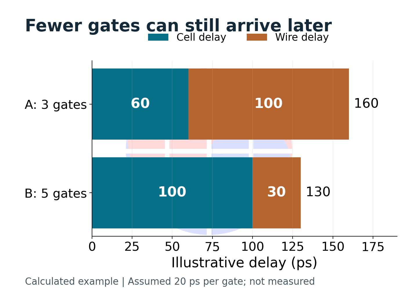
Where the savings in logic depth can disappear
Consider hypothetical paths. Implementation A has 3 gates taking 20 ps each, with 100 ps of total wire delay. Implementation B has 5 gates taking 20 ps each, but only 30 ps of wire delay. The totals are 160 ps for A and 130 ps for B. A has fewer gates and arrives later.
These are arithmetic assumptions that separate components of a delay budget, not measurements from a real cell library. Actual cell delay also changes with input transition time and output load. Multiplying logic depth by a constant delay is therefore inadequate for evaluating a design.
The key questions are how many inputs a signal drives and where those inputs sit. Sharing an intermediate result among consumers simplifies the logic expression. If the consumers are distant, however, the shared source must drive the capacitance of both the wiring and the receiving pins.
Duplicating some logic near its consumers can reduce each branch's load. The price includes extra cell area, leakage and additional load on upstream inputs. Our editorial interpretation is that cloning must be assessed across the surrounding paths, rather than only at the shared node.
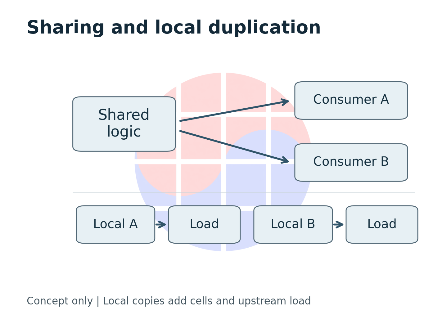
Cells implementing the same function can have different drive strengths and input capacitances. A stronger cell may help its output while slowing the preceding stage. Showing only the improved segment of a timing report can hide delay that moved elsewhere.
Cell area and chip area also need separate treatment. Reducing the sum of standard-cell areas does not automatically shrink a die whose core dimensions and macro placement remain fixed. Agreeing whether an area metric describes cells or the placement region is necessary to interpret a performance-cost tradeoff.
| Change | Possible benefit | Cost to inspect |
|---|---|---|
| Share logic | Fewer cells | Fanout and long routes |
| Clone logic | More local loads | Area and upstream load |
| Upsize a cell | Stronger drive | Input capacitance and leakage |
| Insert buffers | Split a long load | Extra cells and hold effects |
This is a comparison framework, not an ordering of preferred moves. When wire delay dominates a path, repeatedly changing cell strength may offer limited benefit. In a congested region, even finding legal space for additional cells can constrain the choice.
The evidence changes as wiring becomes concrete
Before placement, a model stands in for physical information that is not yet fixed. Placement supplies pin locations; global routing adds topology and layer information. OpenROAD documents separate parasitic-estimation stages for these cases. Parasitics estimation
Parasitics are the resistance and capacitance introduced by wires beyond their intended logical function. Equal wire lengths need not imply equal delays: layers, branching and loads matter. Nearby placement coordinates can still require a detour, changing the result expected from straight-line distance.
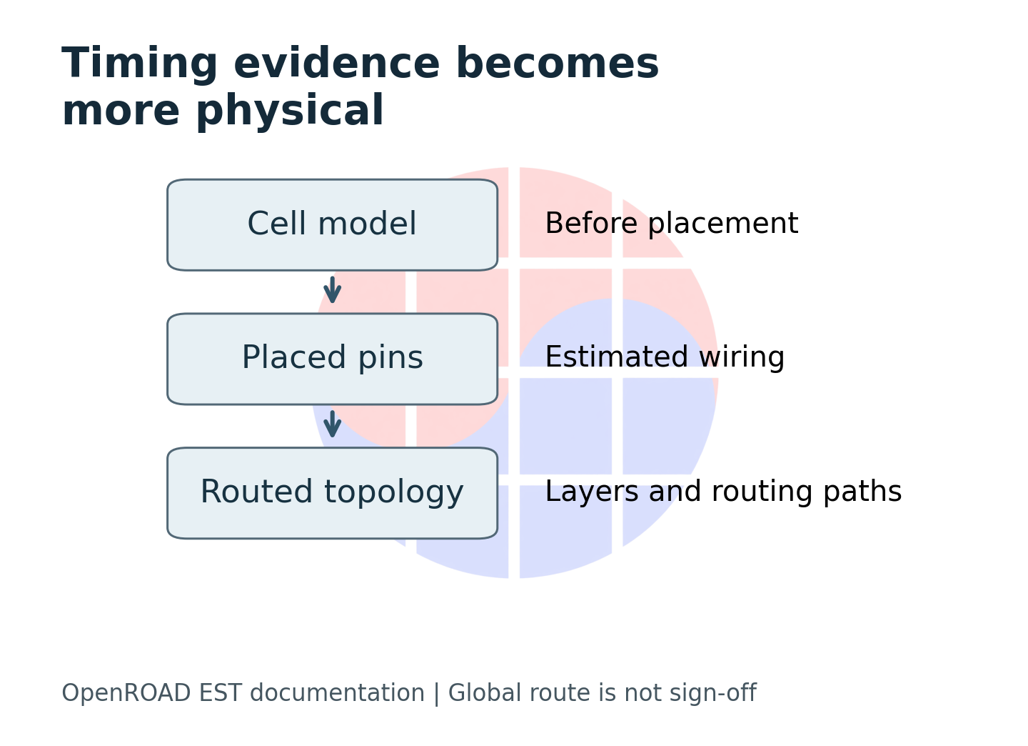
A more concrete global-route estimate is still not final extraction. A timing value needs an implementation stage and parasitic model beside it. Mixing stages can confuse the effect of an optimization with the effect of a more detailed model.
Static timing analysis, or STA, combines physical information with timing constraints. OpenSTA accepts Liberty cell data, SDC timing constraints and SPEF parasitics, among other inputs. These serve different purposes, so identical circuit files do not establish identical timing conditions. OpenSTA
| Evidence stage | What it can support | What it cannot establish alone |
|---|---|---|
| Cell-based estimate | Candidate screening | Routed timing closure |
| Placement estimate | Position-aware comparison | Final routing parasitics |
| Global-route estimate | Topology-aware evaluation | Final sign-off across corners |
| Final extracted analysis | A specified sign-off check | Unchecked modes or corners |
Fixing the clock period alone can appear sufficient for a fair comparison. Yet input delay, output load, clock uncertainty and path exceptions can change the slack of the same data path. A useful handoff binds the improved result to the settings that produced it.
Comparing an initial synthesis estimate with a final routed estimate is also a poor way to calculate an improvement. Run both the reference and candidate from the same starting state through matched downstream steps, then compare reports at the same point. Without that experiment design, adding more sophisticated algorithms makes causality harder to explain.
When the logic structure itself needs another choice
Some paths remain limited by their Boolean decomposition after drive-strength adjustments and buffering. Remapping searches for alternative cell combinations implementing the same function. A local approach works on a bounded region while preserving its interface to the surrounding circuit.
The study's PCR method considers surrounding timing, loads and estimated interconnect when proposing candidates, then subjects them to physical evaluation. It separates a candidate that scores well in a model from one accepted after placement and routing analysis. That feedback loop is the central methodological idea. Paper methods and evaluation
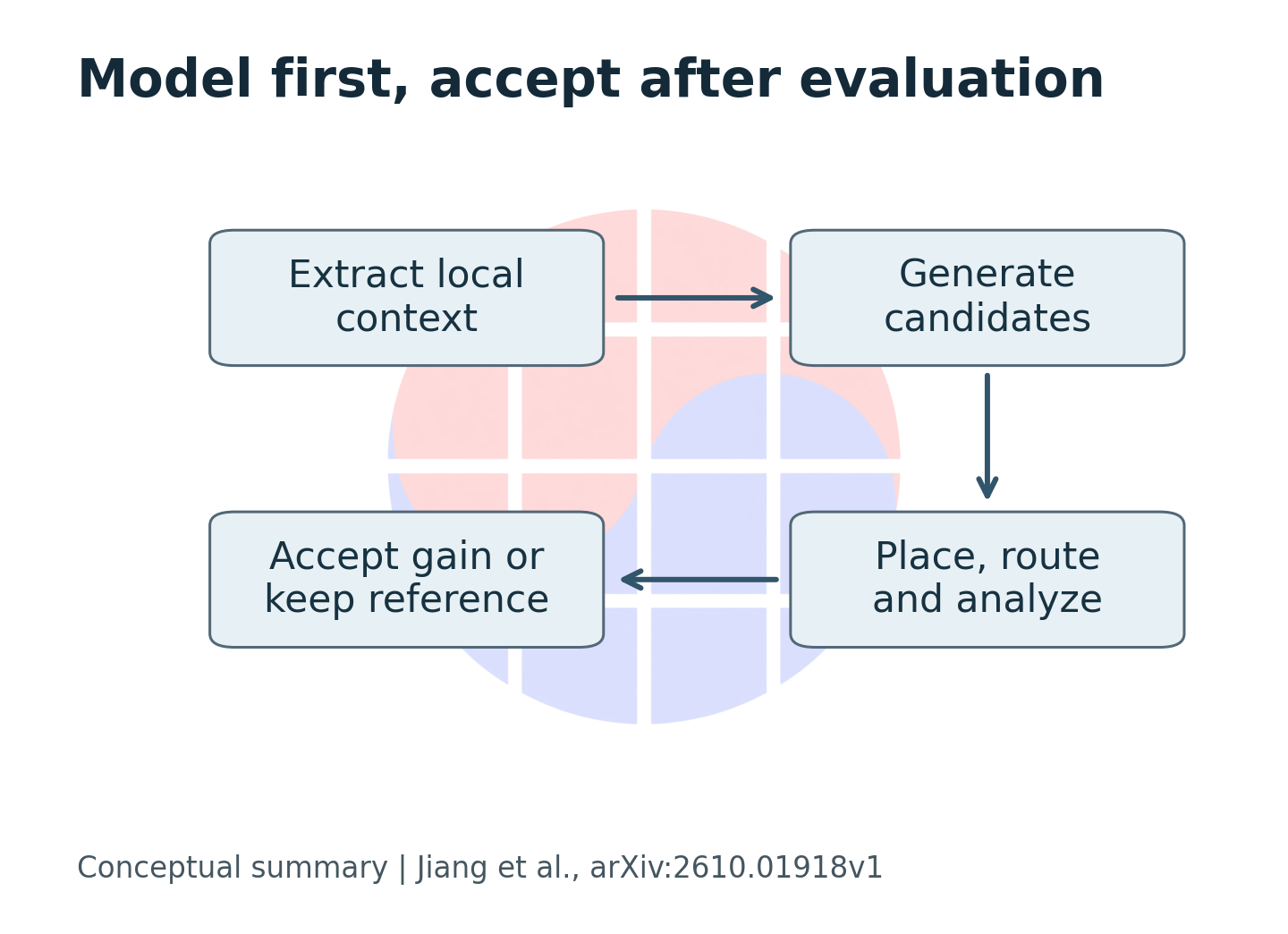
The same distinction helps teams evaluate tools. Candidate generation should examine alternatives cheaply; acceptance should reject false improvements even when evaluation is expensive. Applying the most expensive analysis to every candidate limits exploration, while accepting on a simple prediction risks later reversals.
Choosing a smaller region is not free either. It reduces the search burden but misses restructuring opportunities outside the boundary. A larger region expands the available choices alongside runtime and placement disruption. Search scope and time budget belong beside the reported outcome.
| Decision | Fast screening | Acceptance evidence |
|---|---|---|
| Timing | Estimated arrival | Matched physical analysis |
| Function | Candidate construction checks | Formal equivalence in the team flow |
| Feasibility | Search result | Legal placement and routing checks |
| Value | Predicted gain | Gain after downstream repair |
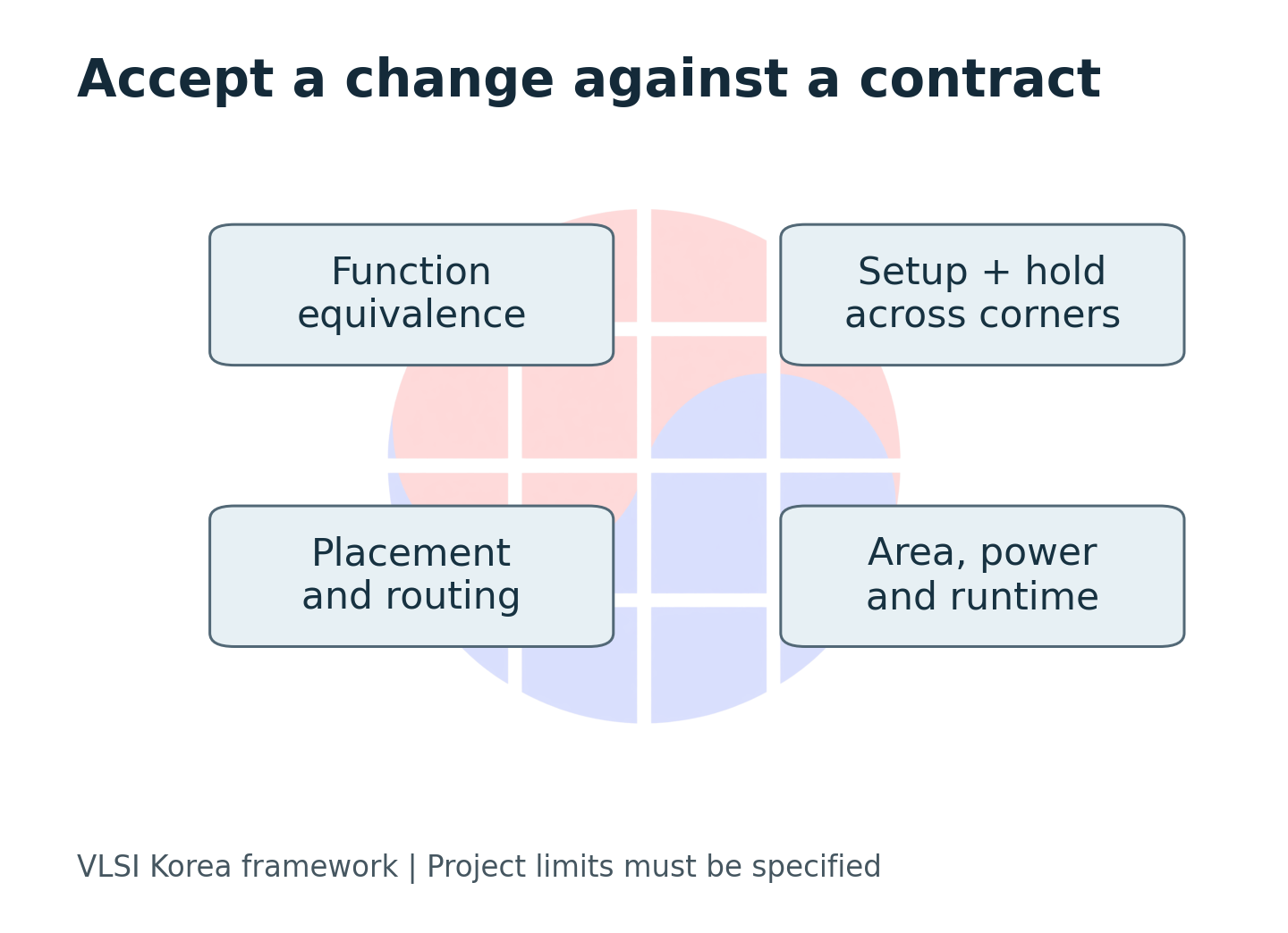
Formal equivalence here is VLSI Korea's recommendation for team adoption, not a claim that the paper completed every commercial verification procedure. Functional equivalence and satisfaction of a timing constraint require different evidence. Passing either cannot substitute for passing the other.
Responsibilities should also be explicit. Logic designers establish intended functionality and permissible transformations, physical designers establish implementation constraints and parasitic models, and verification engineers check equivalence and valid timing exceptions. Automated candidate generation makes these acceptance boundaries more important.
Separate an algorithm's contribution from its flow
The paper's tables contain a consequential qualification. Only 2 of the 9 position-aware comparison cases accept a remapping update. In the other comparison, all 7 cases retain their input mappings. The full tables therefore cannot be read as improvements caused entirely by remapping. Paper Tables I and II and results discussion
VLSI Korea view: Evidence that a complete flow improves results and evidence that a particular optimization caused the gain should be requested separately.
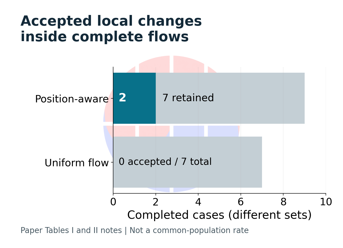
This qualification sharpens the question rather than eliminating the research value. Preserving an existing implementation when candidates are worse can be useful. But that addresses a different question from how much faster new logic became: it also concerns how well a flow protects a good starting point.
Readers should first identify the baseline. An initial circuit, the same circuit with matched postprocessing but no optimization, and a competing algorithm's output establish different comparisons. Even an identically named design needs separate treatment when its downstream processing differs.
| Claim | Evidence needed |
|---|---|
| The complete flow improves timing | Matched end-to-end runs |
| Remapping itself causes the gain | Same-flow ablation with and without remapping |
| The method generalizes | Broader cases, corners and repeatable settings |
| The result is production-ready | Full project sign-off and integration evidence |
WNS describes the worst negative slack, while TNS captures an aggregate of violations. The worst path can improve while violations at other endpoints grow, so both matter. Ratios between totals from different tools are weak evidence unless their path and endpoint aggregation conventions are understood.
Our recommendation is straightforward: alongside comparisons with competing methods, request an experiment that disables only the optimization inside its own flow. If that is unavailable, lower confidence in an adoption decision and run a bounded internal evaluation. Do not fill the missing experiment with an estimate or turn benchmark advantages into commercial-chip performance claims.
What Korean design teams should compare first
For Korean fabless companies, design-service teams and university labs, a small experiment under matched conditions is a useful starting point. There is no need to upload a customer's private design to an external service. Use authorized internal environments or public examples and trace the cause of a change around a bottleneck path.
VLSI Korea recommends recording input revision, constraints, library identifiers, physical evaluation stage, tool settings and results together. This does not require sharing library or process contents. Approved identifiers that let the team recover the same conditions internally are sufficient.
Compare cell and wire delay, load and transition time along the same path before and after optimization. When the critical path changes, retain both the previous and the new worst paths. Keeping only the newly improved path makes it easy to confuse a shifted bottleneck with a solved problem.
Check setup and hold together. Earlier arrival can help setup while creating a hold problem if data arrives too soon. OpenROAD documents separate setup and hold repair, including ordering and their interaction. Gate Resizer
| Keep fixed | Compare | Reject or investigate |
|---|---|---|
| Modes and corners | Setup and hold | A new failing corner |
| Constraints and exceptions | WNS and TNS | Improvement from relaxed constraints |
| Starting physical state | Cell and wire delay | Unmatched evaluation stages |
| Tool and resource budget | Runtime and accepted changes | Hidden repair or search costs |
Area and power carry separate costs. If cloning buys timing, check whether the price is acceptable. Leakage alone cannot establish a dynamic-power improvement; activity and power-analysis conditions also matter. Without agreed performance, power and area priorities, tool outcomes can end up defining the team's objectives.
Tools that reach silicon, and the evidence to watch
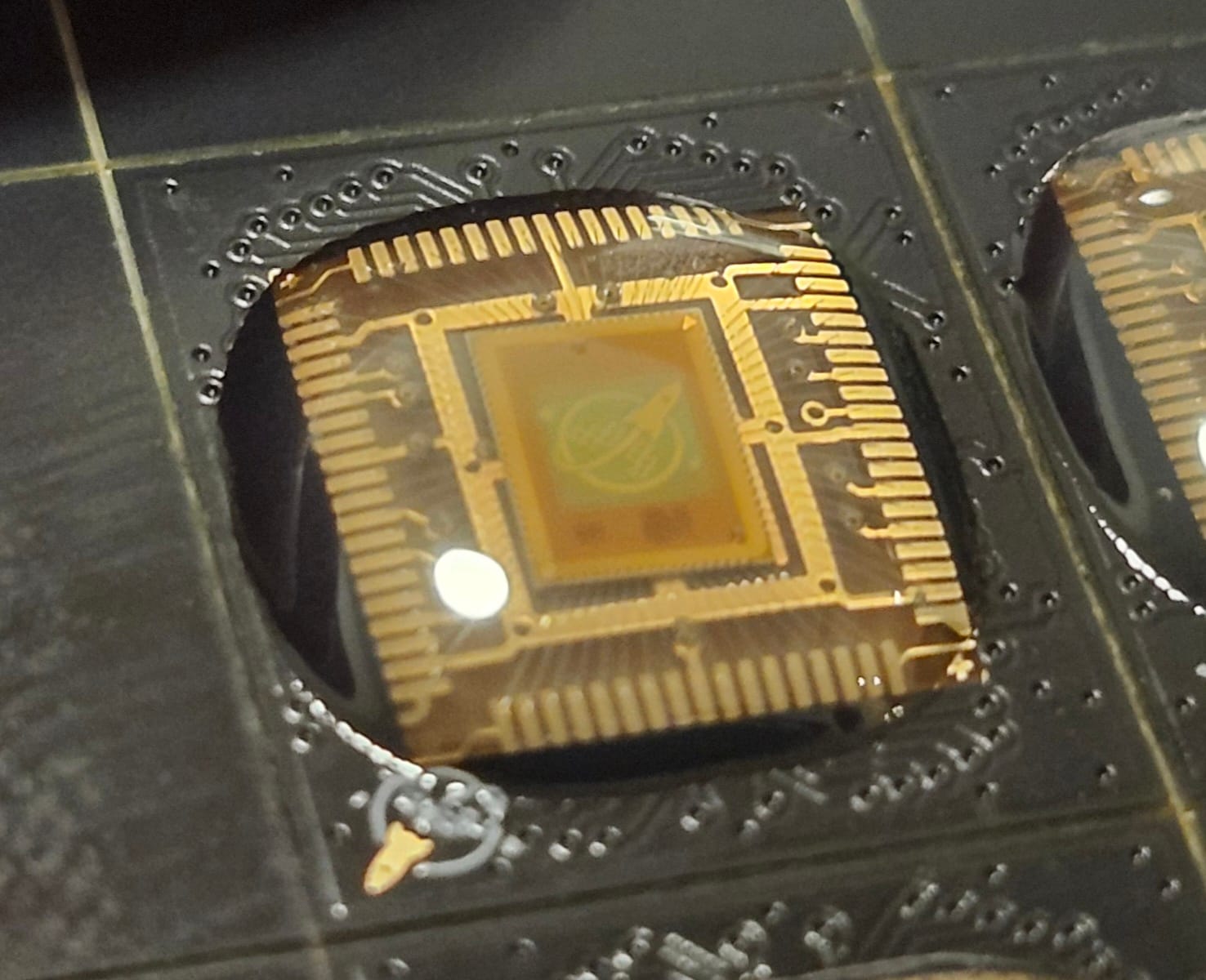
This discussion extends beyond educational logic diagrams. OpenROAD lists Tiny Tapeout and wafer.space as routes to physical chips. Wafer.space's official repository supplies photographs of actual Run 1 chip-on-board parts. This case connects design tooling to hardware; the photograph does not establish measured PCR performance. OpenROAD ecosystem · wafer.space source
Over the next 6–12 months, look beyond the largest improvement percentage. Watch for matched-flow comparisons with remapping enabled and disabled, records of accepted changes and their locations, reproducibility across broader designs and corners, and runtime. Such evidence would connect a modeling idea to a team's adoption decision.
If gains disappear after detailed routing or under other operating conditions, or if area and power exceed the team's limits, narrow the adoption scope. Those are conditions that would change this article's judgment. Timing optimization succeeds through the slack that survives agreed evaluation conditions and the price paid for it, rather than through the shortest logic expression.
Sources and scope
PCR v1 was read beyond its abstract, including methods, tables and notes. It is a preprint; conference acceptance and measured silicon results are not established here. OpenROAD and OpenSTA documentation supports tool behavior, not independent reproduction of PCR performance. Calculations and diagrams are original explanatory material.