VLSI Korea
What does PASS prove when AI repairs HLS code?
Executable tests are a starting point for automated repair. Distinguishing test inputs, result checking and post-synthesis verification keeps source-level success from being mistaken for hardware success.


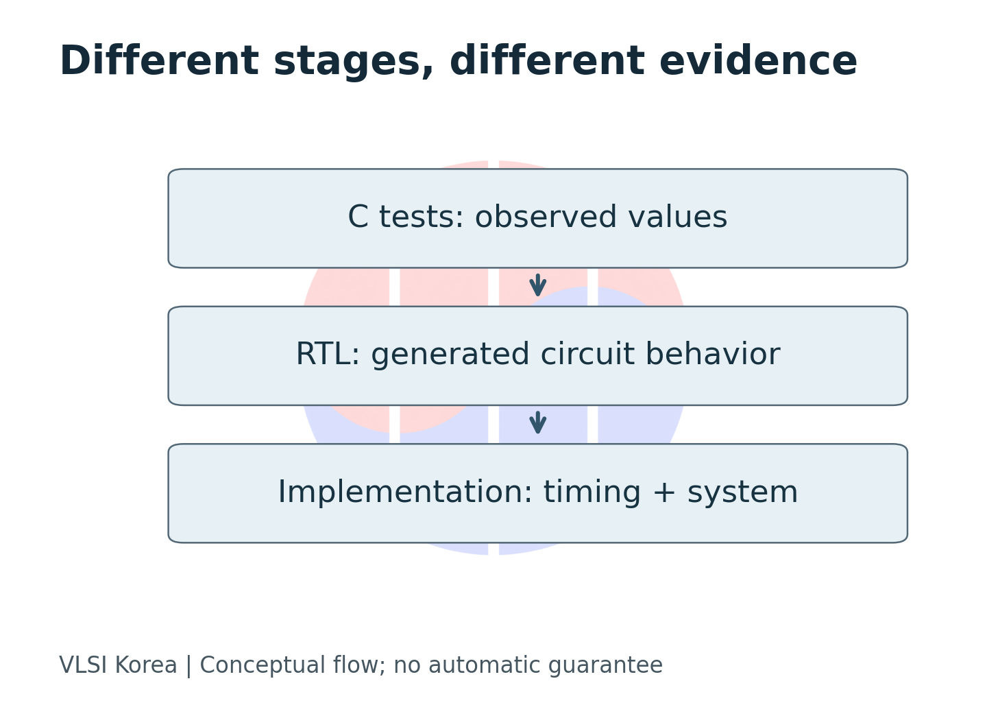
An HLS repair tool displays a green PASS. Is that enough to move an accelerator design forward? The answer depends on the check behind the label. It might mean that a compiler accepted the source, or that outputs matched reference values for the supplied inputs. Verification of a synthesized circuit requires separate evidence. Engineers need a record explaining the scope of the result alongside the success indicator.
A University of New Hampshire study in the latest public listings makes this question timely. Its authors evaluated 125 bug instances with executable checks. The scope is C-level functional repair; post-synthesis correctness is outside it. Starting from that distinction, this article considers the evidence an engineering team should add. The calculations and examples below are original VLSI Korea teaching examples, not reproductions of the paper’s measurements. Study
| Study scope | Beyond the reported experiment |
|---|---|
| Executable C-level repair checks | Generated-RTL correctness and physical implementation |
Between a correct source file and a working chip
High-Level Synthesis translates algorithms expressed in C or C++ into hardware structures. It must decide where operations execute and how they are scheduled, bringing software behavior and circuit constraints into the same workflow. First identify what a repair changes: the algorithm, synthesis directives or an interface. Applying the same acceptance rule to different targets can admit a patch that preserves results while losing required performance.
The actual photograph in this article shows an early Altera FPGA, the Cyclone EP1C3. Its central logic array and peripheral circuitry make the physical destination of an implementation concrete. Published in 2013, it is a historical reference photograph, not a device evaluated in the study or a claim of support by current tools. An FPGA configures logic, routing, memory and input-output resources through a bitstream. Correct computation in a C file alone cannot establish the interfaces and timing of the resulting physical design. Original photograph, Altera’s FPGA explanation
| Evidence | Question answered | Still open |
|---|---|---|
| Compilation | Is this source accepted? | Functional correctness |
| C test | Do observed outputs match? | Untested inputs, RTL behavior |
| RTL co-simulation | Does generated RTL pass these tests? | Physical timing, system behavior |
| Implementation and board test | Does this configured system meet its checks? | Untested operating conditions |
A written functional contract clarifies the scope. “Sum the valid elements of an input array” leaves several questions unanswered: is an empty input legal, what are the sign and range of the values, and what happens on overflow? Inferring those answers backward from an implementation risks treating a bug as the specification. Separate behavior that must remain unchanged from implementation choices that may change. The checker should independently assess the stated requirements.
Before reading a pass rate, ask what inputs were supplied and what the outputs were compared against. (VLSI Korea editorial interpretation)
First establish that the test can fail
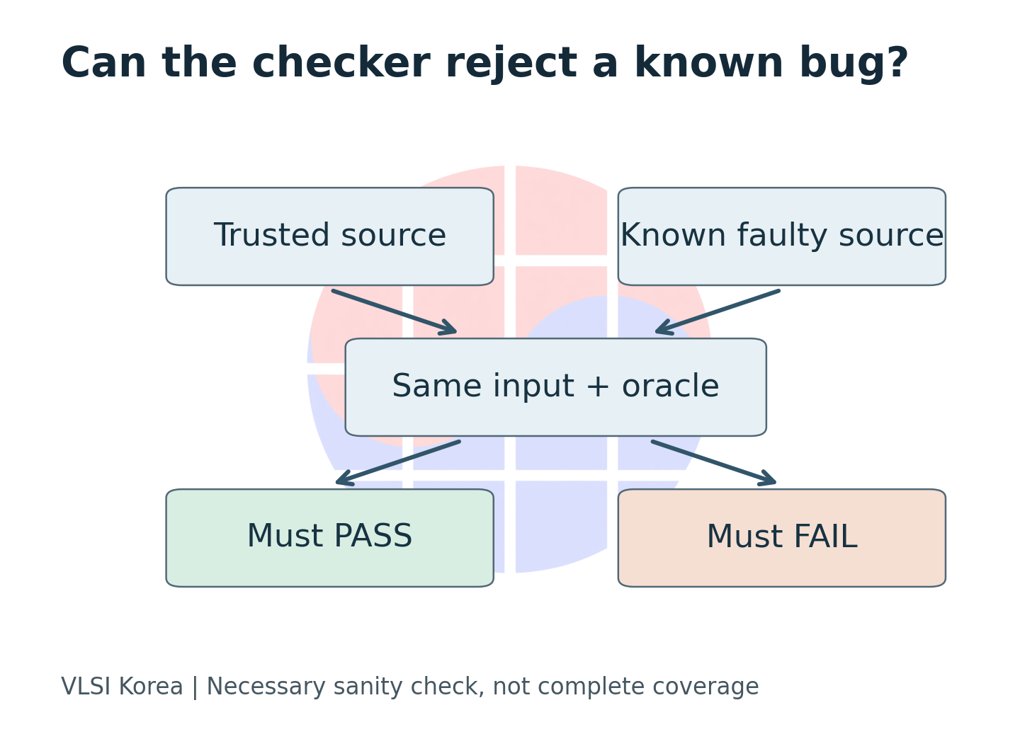
An oracle is the mechanism that judges an execution result against an expected answer. Copying an original program’s behavior differs from verifying a requirement. If the original is wrong, a copied reference may inherit the mistake. Conversely, if a deliberately broken implementation still passes, the test cannot detect that particular defect. Before comparing repair models, a team can check whether its oracle distinguishes a trusted implementation from an intentionally faulty one.
CHStone is a collection of C-based HLS benchmarks drawn from different applications. Its paper’s abstract describes a resource for quantitative evaluation of design ideas and tools. Reusing such kernels for repair evaluation requires checking whether the original purpose matches the needed defect-detection scope. Inputs useful for comparing design performance do not automatically expose every functional bug. CHStone abstract
Consider a small accumulator that returns the sum of the valid elements of an integer array. For this example, an empty input has sum 0, and none of the inputs overflows. The trusted implementation adds every valid element; the faulty one omits the last. For [1, 2, 3], the correct output is 6 and the faulty output is 3. This test distinguishes the omission, but it cannot establish that an arbitrary repair is correct.
| Checker sanity test | Expected result | Interpretation |
|---|---|---|
| Trusted sum on [1, 2, 3] | 6, pass | Positive control works |
| Omit last element | 3, fail | This defect is observable |
| Always return 6 | 6, pass | A false repair can still pass |
The last row matters. A patch that always returns 6 passes the single input without implementing a sum. Making a defect observable is weaker than excluding incorrect repairs. A failed test on an injected bug should therefore not turn that test into a complete specification. Record which input exposed which difference, so the next stage can identify missing behavior.
Add inputs that separate competing answers
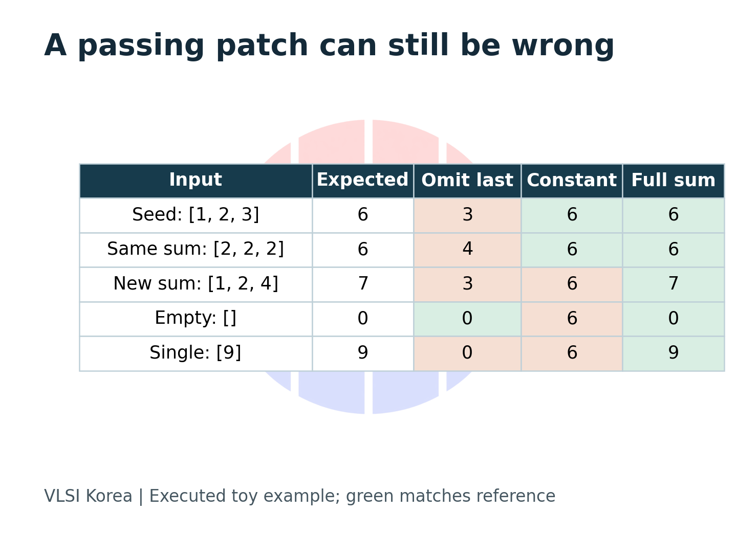
The number of tests matters less than whether they distinguish candidate implementations. Adding [2, 2, 2] to the accumulator tests produces another sum of 6. It does not reject the constant-return patch. Changing the input to [1, 2, 4] produces an expected sum of 7 and immediately separates the candidates. Empty and single-element inputs exercise loop boundaries. Rather than changing values without a purpose, describe which failures the length, boundary or value distribution is intended to expose.
It is also useful to distinguish validation inputs from those shown to the repair system. Repeatedly providing the same tests may encourage a tool to satisfy the visible checks rather than the intended behavior. Reviewers can run held-out inputs separately and record the rule tested by each added failure case. A finite held-out set still cannot prove completeness, but it provides additional opportunities to reject patches fitted only to the visible examples.
| Input class | Example here | Intended distinction |
|---|---|---|
| Seed | [1, 2, 3] → 6 | Known missing-element bug |
| Same total | [2, 2, 2] → 6 | Does not reject constant output |
| Changed total | [1, 2, 4] → 7 | Rejects constant output |
| Boundary | [] → 0; [9] → 9 | Empty and single-element handling |
The official MachSuite README warns of a portability issue in its validation approach and says the final output check is not performed. This does not establish that every subsequent study has a broken checker: researchers may build their own harness. The practical lesson is to inspect the actual version, harness, failure return value and comparison path instead of assuming a repository name establishes verification capability. A successful exit code does not justify counting a functional pass if the comparison routine never ran. MachSuite repository
Repeating the same answer does not establish correctness
Different patches on successive attempts deserve investigation. The description may be incomplete, the failure may be poorly localized, or generation may simply be diverse. Yet different text does not necessarily mean different behavior. A for loop and a while loop can compute the same sum over the defined input domain. Conversely, a model that always returns the constant 6 can produce the same wrong answer consistently.
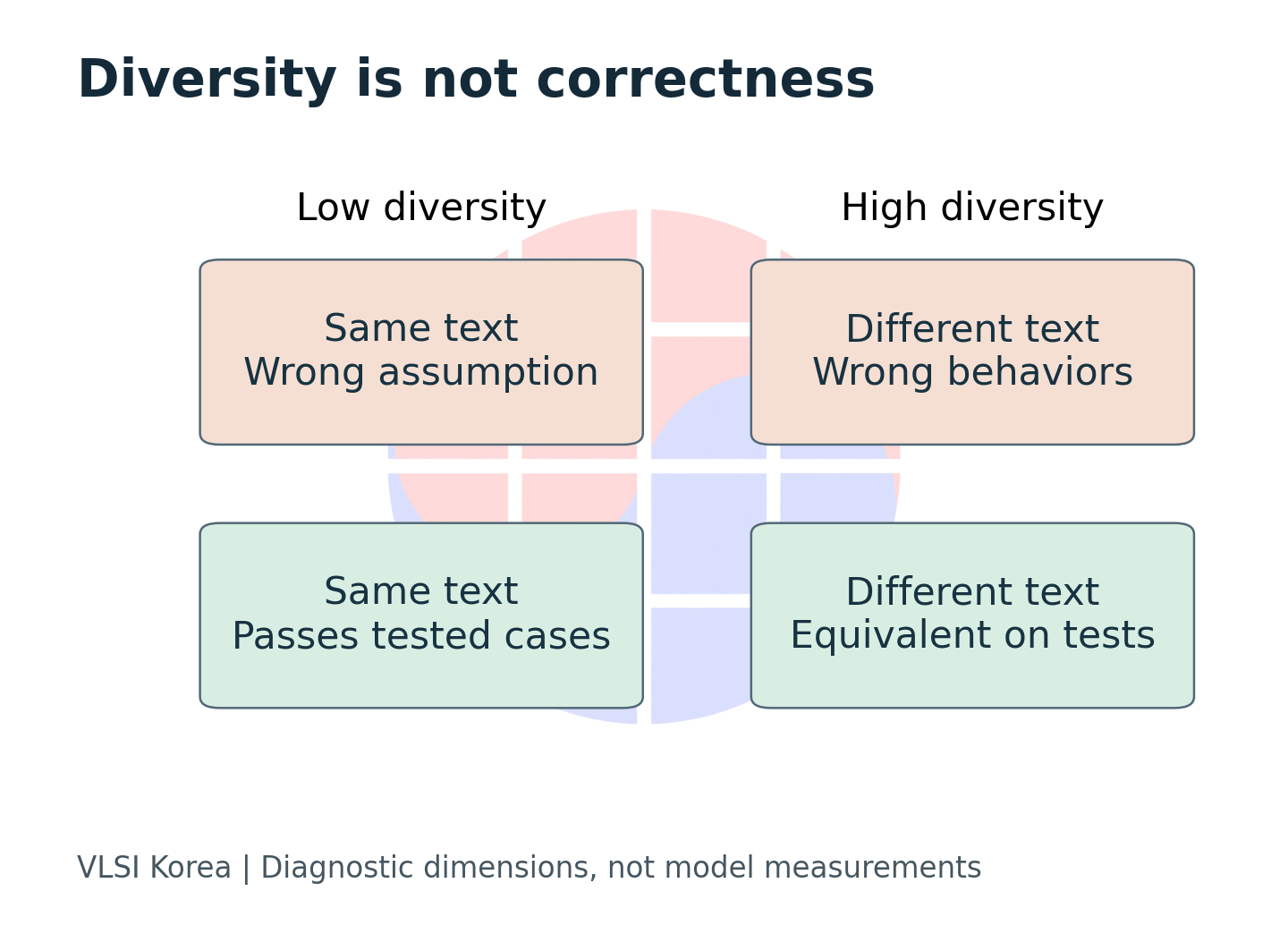
Patch diversity is therefore useful as a clue for choosing the next check. Finding inputs on which candidates disagree can strengthen the oracle. If every candidate fails the same boundary case, revisit the contract or input domain. If only one candidate fails to compile, separate syntax and type errors first. These diagnostics produce information for the current design without pretending to establish a model’s general capability.
| Repeated outcome | Next question |
|---|---|
| Same patch, tests fail | Is the model repeating one wrong assumption? |
| Different patches, same tested outputs | Which new input distinguishes their behavior? |
| Different patches, different failures | Is the defect localized and the contract explicit? |
| Tests pass consistently | What remains outside these tests? |
The same principle applies to comparison tables. Changing the attempt budget or test inputs changes the meaning of a success rate. Getting a repair right on the first attempt and finding one passing candidate among several do not imply equal selection cost. More generation can add testing time or synthesis queues. Choosing a model requires accounting for the effort of identifying an acceptable candidate and why candidates fail later stages, not merely whether a passing answer exists.
Carry the repair into RTL and the time domain
AMD’s Vitis HLS documentation describes C/RTL co-simulation as generating inputs from a C testbench, simulating the generated RTL and returning its outputs to the testbench for checking. The testbench must judge its own results. This extends the check to a synthesized circuit, but weak inputs or comparison conditions carry their limitations into that stage. AMD UG1399
An engineering acceptance contract should also describe timing. Correct results can still miss a streaming workload’s requirements if the design accepts new inputs too slowly. Latency is the time from one operation’s start to completion; Initiation Interval is the spacing between successive starts. In the idealized example below, latency is 12 cycles and the interval is 3 cycles. The 4 operations start at 0, 3, 6, 9 and finish at 12, 15, 18, 21. The last completion occurs after 21 cycles.
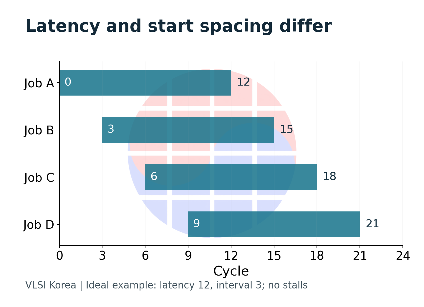
With the same latency but no overlapping operations, completion takes 48 cycles. This is a calculation under stated assumptions, not a product measurement. A repair may preserve results while changing resource sharing or memory accesses and therefore changing the conditions for overlap. In addition to checking values, verify whether the design accepts work at the permitted input rate and delivers results when required.
| Acceptance layer | Record with the patch |
|---|---|
| Source behavior | Input domain, reference result, compiler configuration |
| Generated RTL | Tool version, interfaces, testbench, observed outputs |
| Timing and resources | Clock target, latency, initiation interval, resource limits |
| System operation | Reset behavior, stalls, backpressure, allowed operating conditions |
The contract should address relevant interface stalls, resets during operation and consecutive inputs of changing lengths. This does not mean adding an identical checklist to every design. Select missing cases from the product’s legal operating conditions. Also distinguish a synthesis report’s target frequency from timing results for an actual implementation. Recording functionality and timing separately makes it possible to explain when a functional repair breaks throughput requirements.
Carrying source correctness into hardware requires carrying the conditions of the result, not just its value. (VLSI Korea editorial interpretation)
Keep the denominator visible to Korean design teams
A Korean fabless or FPGA accelerator team adopting automated repair can place a small internal evaluation between public-kernel scores and its own IP requirements. This does not require sending confidential design material to an external service. Begin in an approved environment with public or authorized examples, then assess how well their defects and inputs represent the work. Separate compilation failures, functional failures, post-synthesis failures and unmet performance constraints to reveal where improvement is needed.
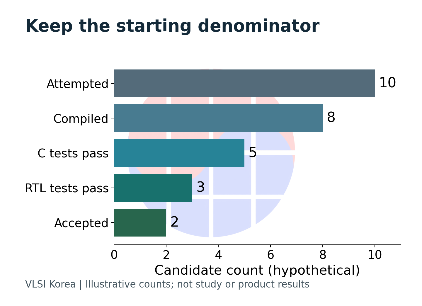
Suppose 10 candidates lose 2 at compilation, 3 at C testing, 2 at RTL testing and 1 at timing or resource acceptance. That leaves 2 candidates. Using only candidates that reached C testing as the denominator obscures the yield of the overall process. Labeling every failure an “AI error” also merges tool configuration problems with functional defects. Track the same starting set and retain the reasons for leaving each stage before comparing adoption results.
| Decision record | Why it matters |
|---|---|
| All attempted candidates | Preserves the denominator |
| Failure stage and reason | Separates configuration from functional defects |
| Human review and tool time | Exposes the cost of finding an acceptable patch |
| Rejected and held-out cases | Prevents easy cases from silently defining the score |
Over the next 6–12 months, the useful development to watch is the connection between verification stages. Do evaluations provide the inputs and oracle version, continue into generated-RTL checks, and retain throughput and resource conditions? Teams can test the value of this proposal internally. If stronger checks uncover almost no additional defects while greatly increasing review time, redesign the input selection and order of checks. Increasing the test count while hiding its total cost is not the objective.
The value of automated repair should be established through faster production of candidates that people can assess. Accepting a candidate into a product design requires a record linking requirements, inputs, the oracle, generated circuitry and implementation conditions. With that record beside PASS, a team can judge what has been checked and what remains for the next stage. That is the form of automation that can earn a lasting place in design work.
Sources and evidence scope
- HLS repair study, arXiv v1: submitted 2026-10-02; observed in the 2026-10-06 public listing. The manuscript states acceptance at ICCD 2026. This is the authors’ acceptance statement, not independent confirmation of a presentation or proceedings publication. The full manuscript was read; experiments were not reproduced. Inconsistencies between abstract and table figures or distribution descriptions mean that model pass-rate comparisons are omitted.
- CHStone: abstract and metadata of the 2009 paper. MachSuite: official README. These are separate research assets, distinct from the accumulator executed for this article.
- AMD UG1399: C/RTL verification procedure in the 2026.1 documentation. Altera: vendor explanation of FPGA configuration.
- ZeptoBars photo, rights: real Cyclone EP1C3 die photograph, used unmodified. Diagrams, tables, decision criteria and accumulator/scheduling examples are original VLSI Korea material, not measured product performance.
AI assisted research and drafting. The illustrative calculations and example were separately checked; this article does not present a reproduction of model performance or physical hardware experiments.
Disclosure
This article is provided for informational purposes only and does not constitute a recommendation to buy or sell any security. Factual statements are based on the cited public research, technical documentation and benchmark materials; illustrative examples and calculations were created by VLSI Korea. Errors may occur in source material or in the preparation of this article. The author may own shares in companies mentioned. All investment decisions and their outcomes are the reader's responsibility.