VLSI Korea
Routing Congestion and Timing: Choosing a Physical Fix or Resynthesis
A red heatmap cannot justify resynthesis alone. Public sources, exact screenshots and assumed-input RC calculations separate the causes of routed timing loss.


A timing regression after routing is not, by itself, a reason to restart synthesis. Separate wire length, load, drive strength and analysis conditions on the same path before deciding whether to change placement, insert a buffer or change the logic.
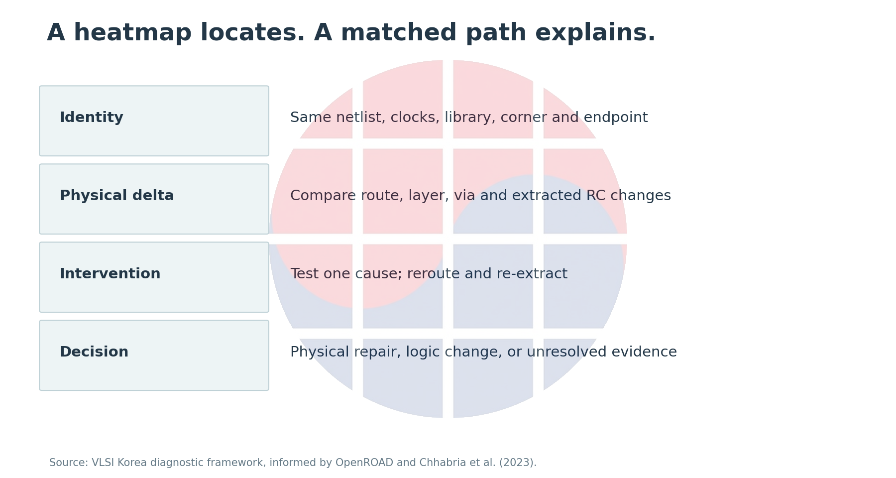
VLSI Korea view: a heatmap tells you where to investigate. Matched net and path deltas tell you which intervention has a defensible cause to address.
This reference serves PD engineers diagnosing a routed timing regression and RTL or synthesis engineers deciding whether a request for resynthesis is justified. The aim is to stop applying the same ECO to failures with different causes.
In the illustrative model below, increasing wire length from 1,000 um to 1,500 um raises the RC first moment from 31.6 ps to 52.4 ps. Every input is a declared teaching assumption, not PDK data or an OpenROAD run. The calculation provides a controlled way to distinguish physical causes from logic limits.
A red display does not identify the same failure
Routing congestion concerns pressure on available routing resources in a region and layer. Placement density measures cell occupancy. Pin access asks whether a legal connection can reach a pin, while detailed-route DRC evaluates completed geometry. These problems interact, but their measurements are not interchangeable.
The following image from the official OpenROAD repository makes that distinction concrete. Its filename and README heading mention congestion, but the selected heatmap in the left panel is Placement Density. Routing Congestion is not selected.
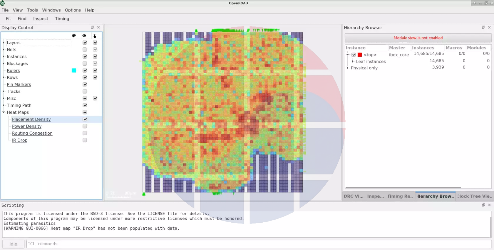
Do not read wire overflow or a timing violation from this picture. It supports an observation about cell occupancy; a routing report must establish which layer and region face additional wire demand. The control visibly selected in the image is stronger evidence than the filename.
A design with low overall utilization can still have a difficult macro channel, pin-access restriction or layer blockage. Conversely, a dense cell region does not establish that every critical net takes a long detour. A universal density threshold cannot distinguish those cases.
The existing P&R reference, in Korean explains the flow and the basic relationship to congestion. This article addresses the narrower question of why a matched path became slower and which experiment should follow. It goes beyond a general instruction to spread the cells.
What changes between an estimated wire and a routed wire?
Spindler and Johannes's 2007 RUDY paper describes distributing a net's estimated wire demand within its bounding rectangle. Its purpose is to estimate aggregate demand efficiently rather than predict every final segment of an individual net.
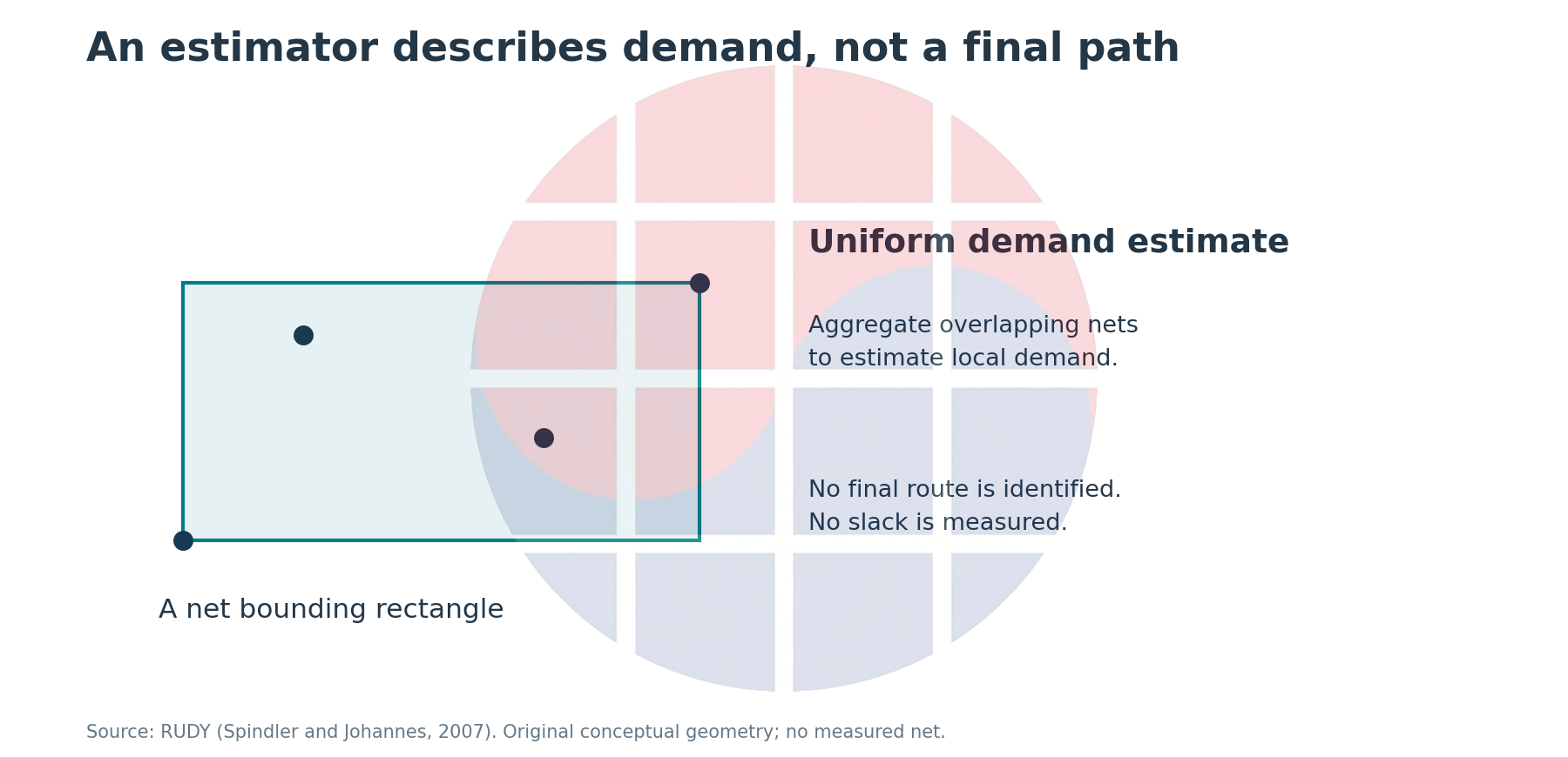
The OpenROAD global-placement documentation inspected on 2026-09-07 separates RUDY-based routability estimation from timing-driven net weighting. Inflating cell area in congested tiles encourages movement; increasing the weight of low-slack nets pursues another objective. These controls negotiate different constraints.
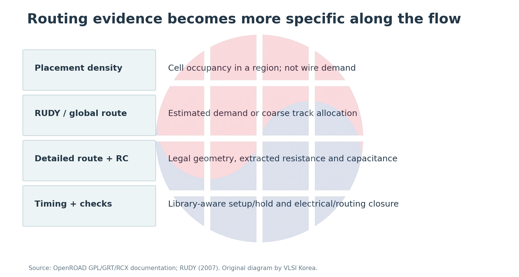
Global routing allocates coarse resources and supplies guidance about paths and layers. Detailed routing must find geometry that satisfies actual pin, via, spacing and other requirements. A connection that looks feasible in a guide may need a detour or a different layer, changing the RC that earlier optimization assumed.
The public manuscript by Chhabria and colleagues, revised 2023-10-02, documents discrepancies that vary with design and tool flow. Its relevant lesson is that a uniform correction factor cannot necessarily resolve the mismatch. The paper's measured improvements are not transferred here into a promise for every current node or design.
Obtaining final geometry still does not make RC independent of its extraction context. OpenRCX documentation describes neighboring-wire distance, context above and below a wire, extraction rules and process corners. A SPEF comparison needs the corresponding geometry and extraction-deck identity.
Together, these sources explain why a placement-to-route timing gap can contain estimation error, detours, layer changes and load changes. In this discussion, RC means resistance and capacitance. It should not be confused with an identically abbreviated routing-congestion metric in a placer report.
Vary length, load and drive separately
The analytical framework is Identity → Delta → Intervention: fix the identity of the comparison, decompose what changed, and test an action directed at that cause. The first calculation isolates the influence of individual electrical inputs.
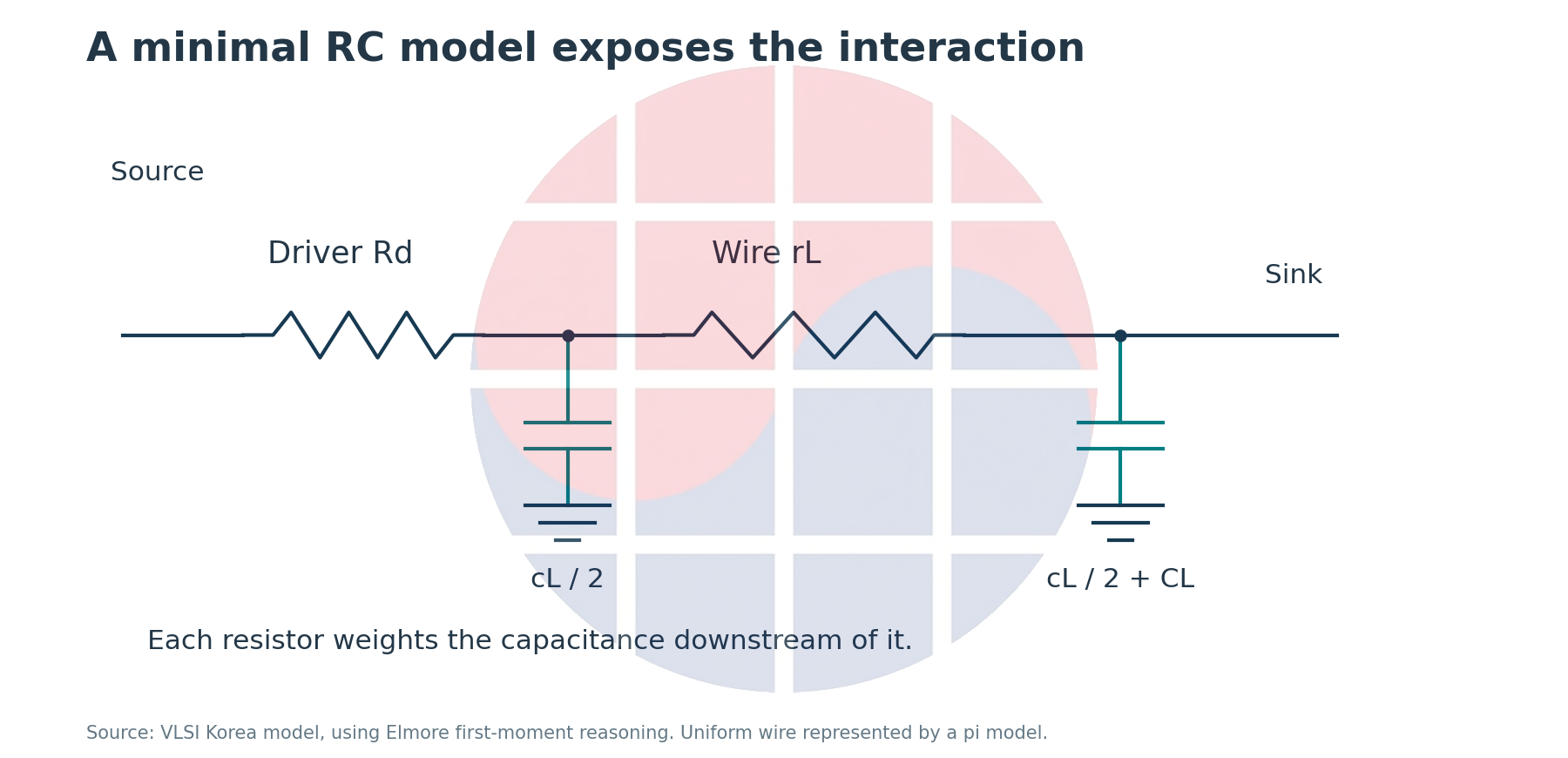
Assume a uniform, unbranched wire. Resistance per length r is 0.08 ohm/um, capacitance per length c is 0.2 fF/um, driver resistance Rd is 100 ohm, and terminal load CL is 20 fF. Summing downstream capacitance against each resistance, as explained in the CMU Elmore-model lecture, gives this first moment:
tau = Rd × (cL + CL) + rL × (cL / 2 + CL)
L is in um. Divide the result in ohm·fF by 1,000 to obtain ps. The first term describes the capacitance driven through the source resistance; the second describes the distributed wire resistance. This is not a signoff calculation of a waveform crossing a specified voltage threshold.
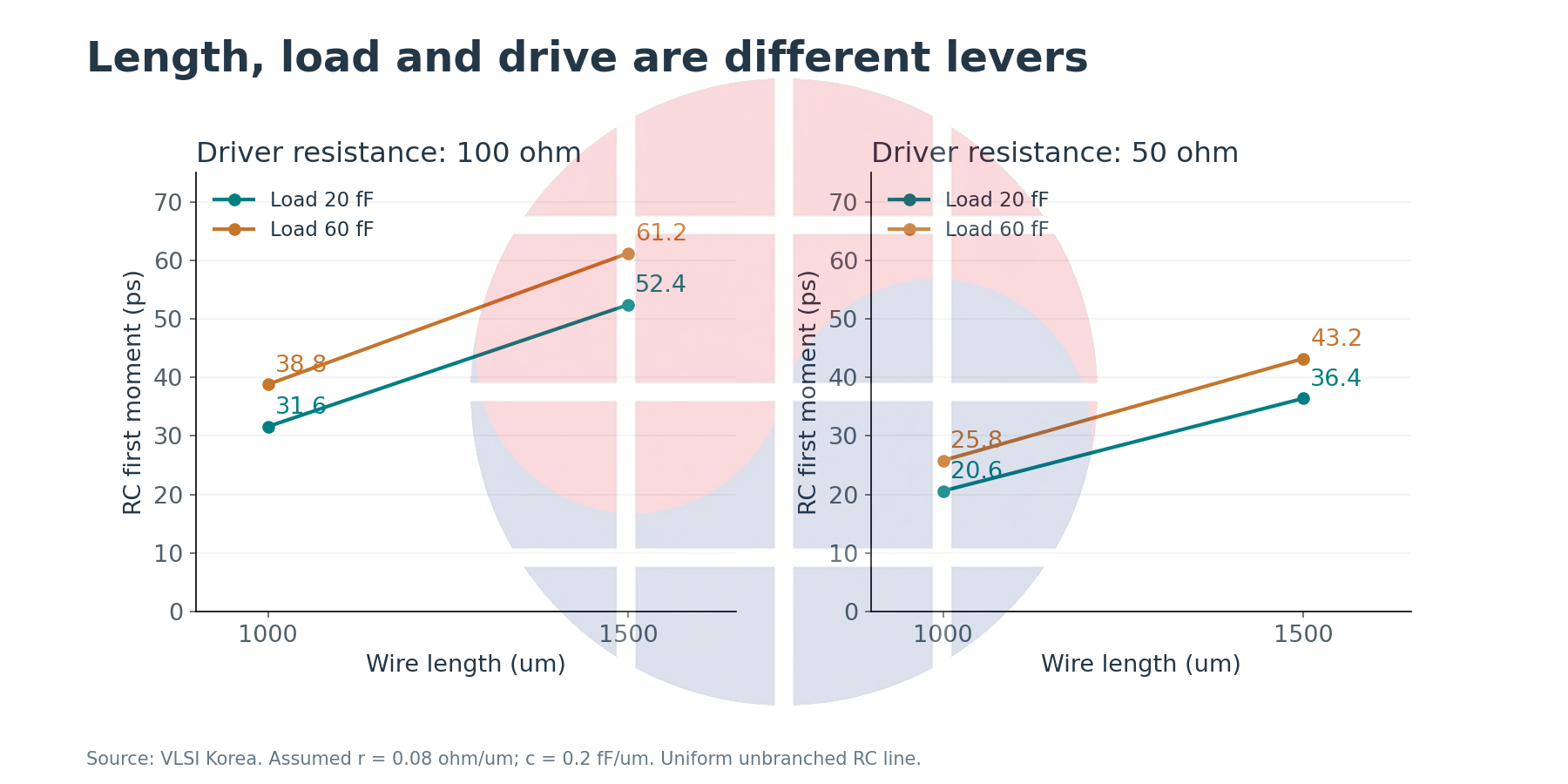
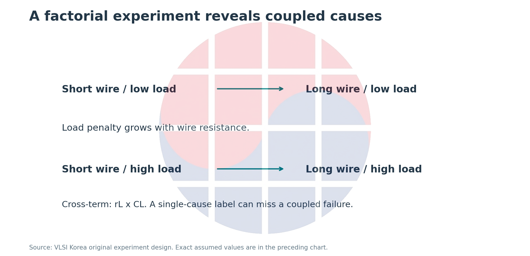
Changing only L from 1,000 um to 1,500 um moves the result from 31.6 ps to 52.4 ps. Keeping the shorter length and changing CL from 20 fF to 60 fF gives 38.8 ps. Changing length and load together gives 61.2 ps, including an interaction of 1.6 ps beyond simply adding the isolated changes.
The interaction comes from rL × CL. The same additional load has a larger effect behind a higher wire resistance. A net with both greater fanout and a detour can therefore resist a clean organizational split into either a wire problem or a cell problem.
A separate experiment lowers Rd to 50 ohm. With CL at 20 fF, the shorter wire gives 20.6 ps and the longer wire gives 36.4 ps. Stronger drive does not remove the distributed wire-resistance term. An actual cell replacement also changes upstream pin loading, area and leakage; these numbers do not establish its net benefit.
The inputs are teaching assumptions for causal separation. Vias, branches, coupling, inductance, nonlinear slew response and variation are excluded. A real ECO requires STA with the appropriate library and extraction conditions. The numerical values should not be transferred to another process node.
Count the buffer's new costs before claiming its benefit
A buffer can break up a long distributed RC line, but it adds input capacitance and intrinsic delay. OpenROAD resizer documentation describes repair of long wires and slew or capacitance violations while explicitly noting the limitations of placement-based estimates of routed parasitics.
Assume a buffer at the geometric midpoint. Its input capacitance is 10 fF, its output resistance is 100 ohm, and its intrinsic delay is 15 ps. Keep the preceding wire and terminal-load assumptions, then sum the first moments of the divided segments and the added intrinsic delay.
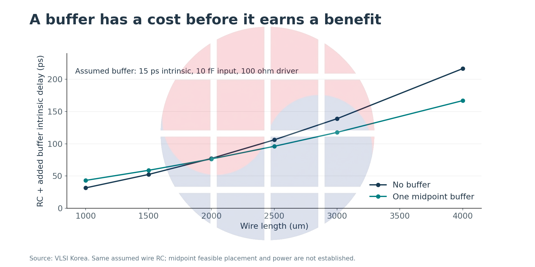
At 1,000 um, the unbuffered 31.6 ps becomes 43.2 ps. At 3,000 um, the unbuffered 138.8 ps becomes 117.6 ps. Under these assumptions, the additional cell costs more than it saves on the shorter wire. The crossing in the plot is not a process-independent insertion threshold.
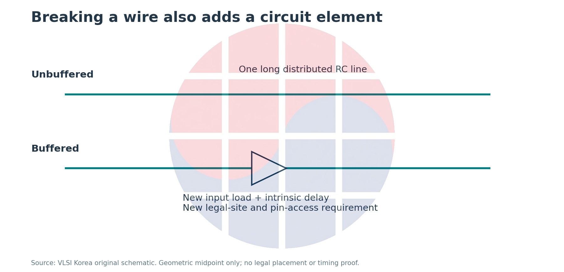
If buffer count rises without a useful WNS improvement, inspect locations and loads before increasing repair effort. The useful position may lack a legal site, additional pins may worsen access, or neighboring nets may take longer routes. A repair can become the input to the next routing problem.
Buffer insertion also changes the netlist. An experiment that holds the netlist fixed while substituting parasitic estimates must be distinguished from an ECO that adds buffers. The former diagnoses the source of error; the latter tests the effectiveness of a modification. Combining them hides the difference between a better model and a better circuit.
VLSI Korea view: buffer count and resizer iterations are not completion metrics. Routed timing, hold, pin access and the other critical paths must survive the repair together.
When should the fix stay physical, and when should synthesis change?
Assume a data-path budget of 180 ps, after allowing for clock-to-Q, setup, uncertainty and the clock relationship. To make the comparison tractable, represent the intrinsic path contribution as a fixed term and add the preceding RC proxy.
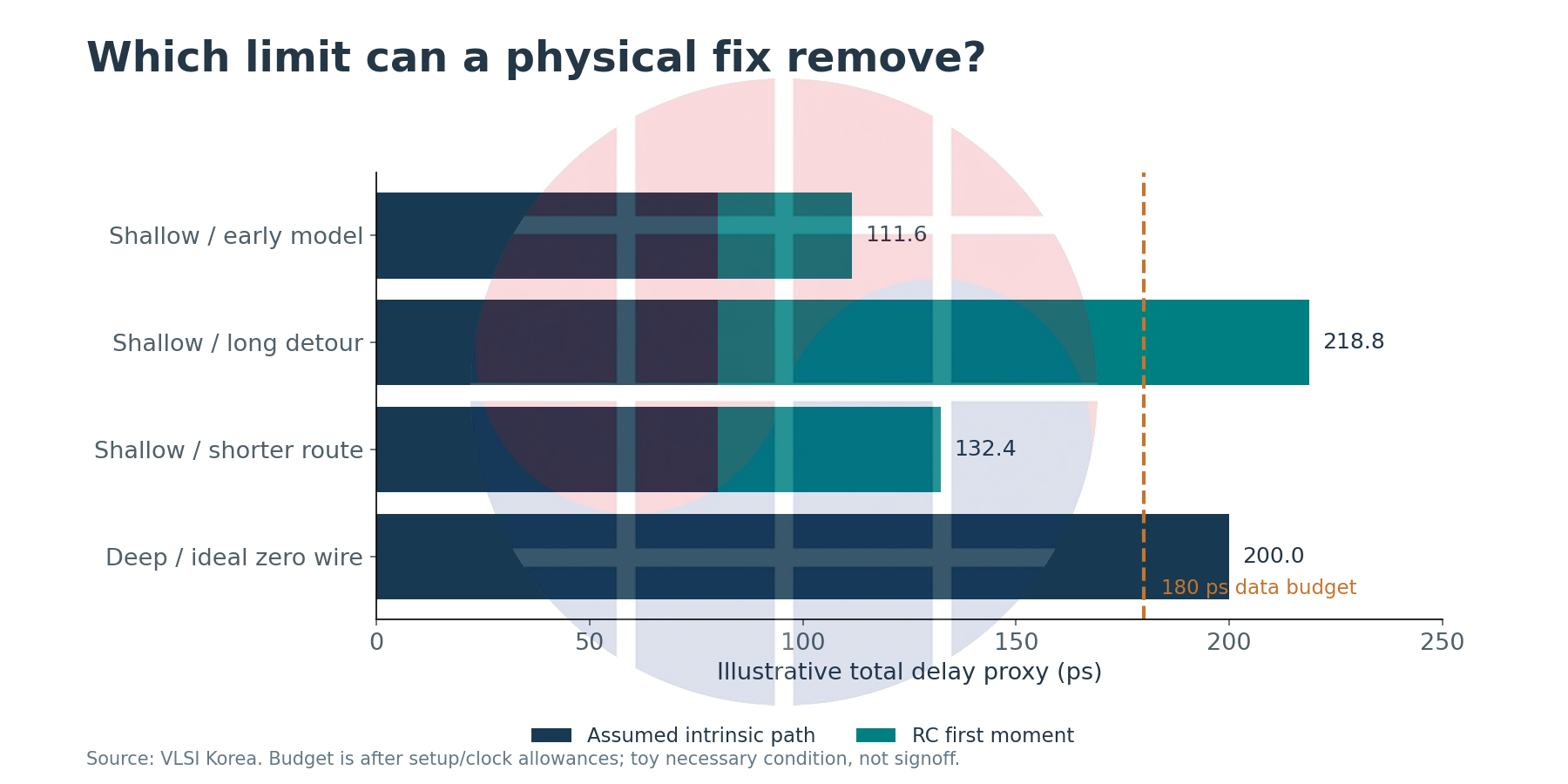
A shallow path with an intrinsic contribution of 80 ps has an early-model total of 111.6 ps. A wire detour to 3,000 um raises the total to 218.8 ps, beyond the budget. If a physical intervention can shorten the wire to 1,500 um without changing the intrinsic term, the total becomes 132.4 ps. This identifies a reason to investigate geometry; it does not prove that such a legal route exists.
In contrast, a deep path with an assumed fixed intrinsic contribution of 200 ps exceeds the budget even after ideal removal of all wire and pin-load RC. The zero-wire row is not obtained merely by setting L to 0 in the loaded circuit. It is an extreme thought experiment that exposes a residual limitation under fixed assumptions.
In practice, the sum of cell delays is not an immutable lower bound. Cell choices, input slew and output load can change it. Review feasible cell choices and physical improvements under validated library conditions before concluding that logic depth, fanout topology, replication or pipeline structure must be reconsidered.
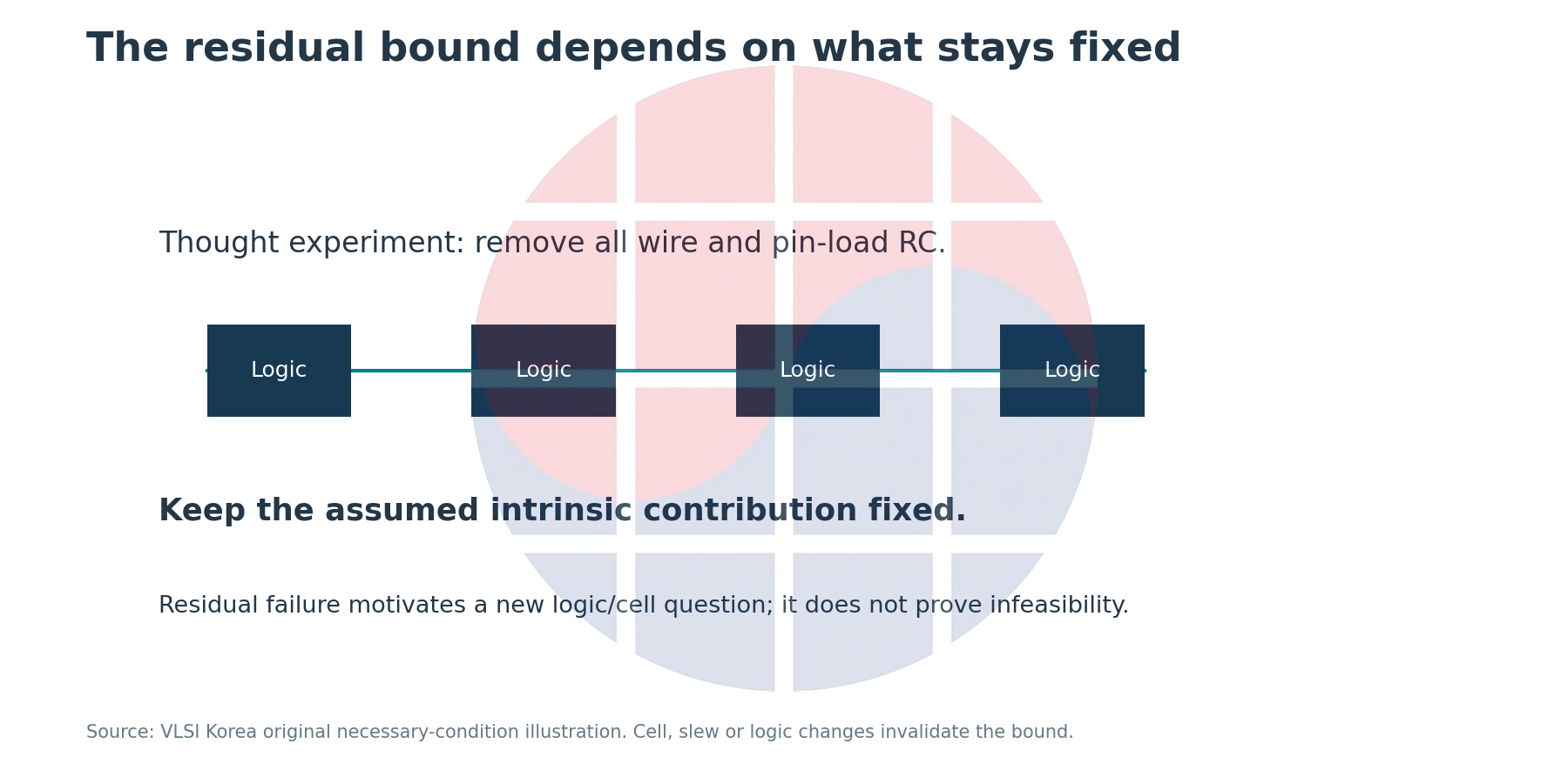
A resynthesis request should include the failing endpoint and path family, constraints, before/after netlist identities, RC deltas, physical interventions already tried and their failure conditions. Explaining which structure persistently demands which resources gives the RTL owner something specific to change.
A logic modification requires renewed equivalence checks and review of latency, protocol and constraint contracts. A physical ECO may remain within an implementation, while changing register boundaries or behavior can expand verification scope. That difference belongs in the schedule estimate.
Freeze comparison identities before assigning a cause
WNS is the worst slack at a particular point in the flow. If another endpoint becomes worst, the change in WNS is not the deterioration of the same path. Compare matched paths or path families first, then inspect the complete violating-endpoint set, TNS and hold results.
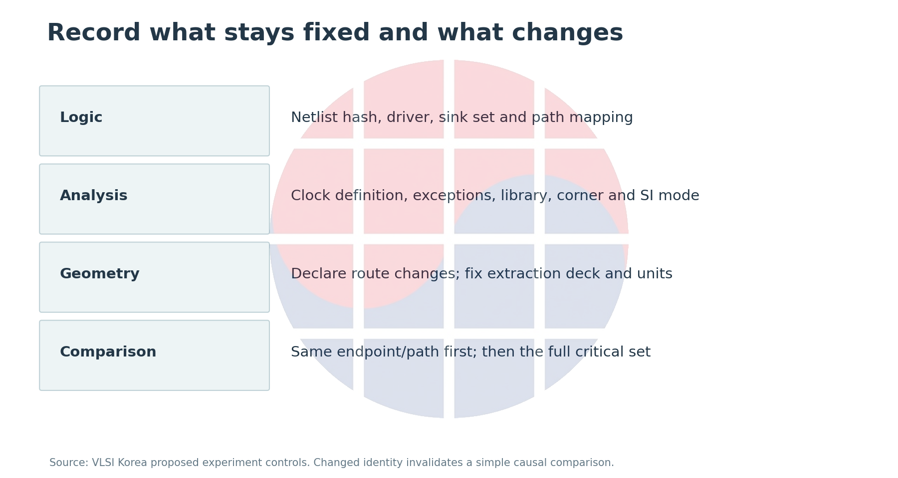
For a diagnostic comparison, hold the netlist hash, driver and sink set, clock definitions, exceptions, library and corner, and SI analysis mode fixed. If placement or routing changes, declare the changed geometry and verify extraction-deck and unit consistency. A changed clock topology prevents attribution of the whole slack shift to data-path RC alone.
Associate each net with route length, length by layer, via changes, total and coupling capacitance, resistance and sink slew. A changed cell sequence requires a structural comparison even when the endpoint name survives. ECOs that remove net names need mapping records to keep the physical issue traceable.
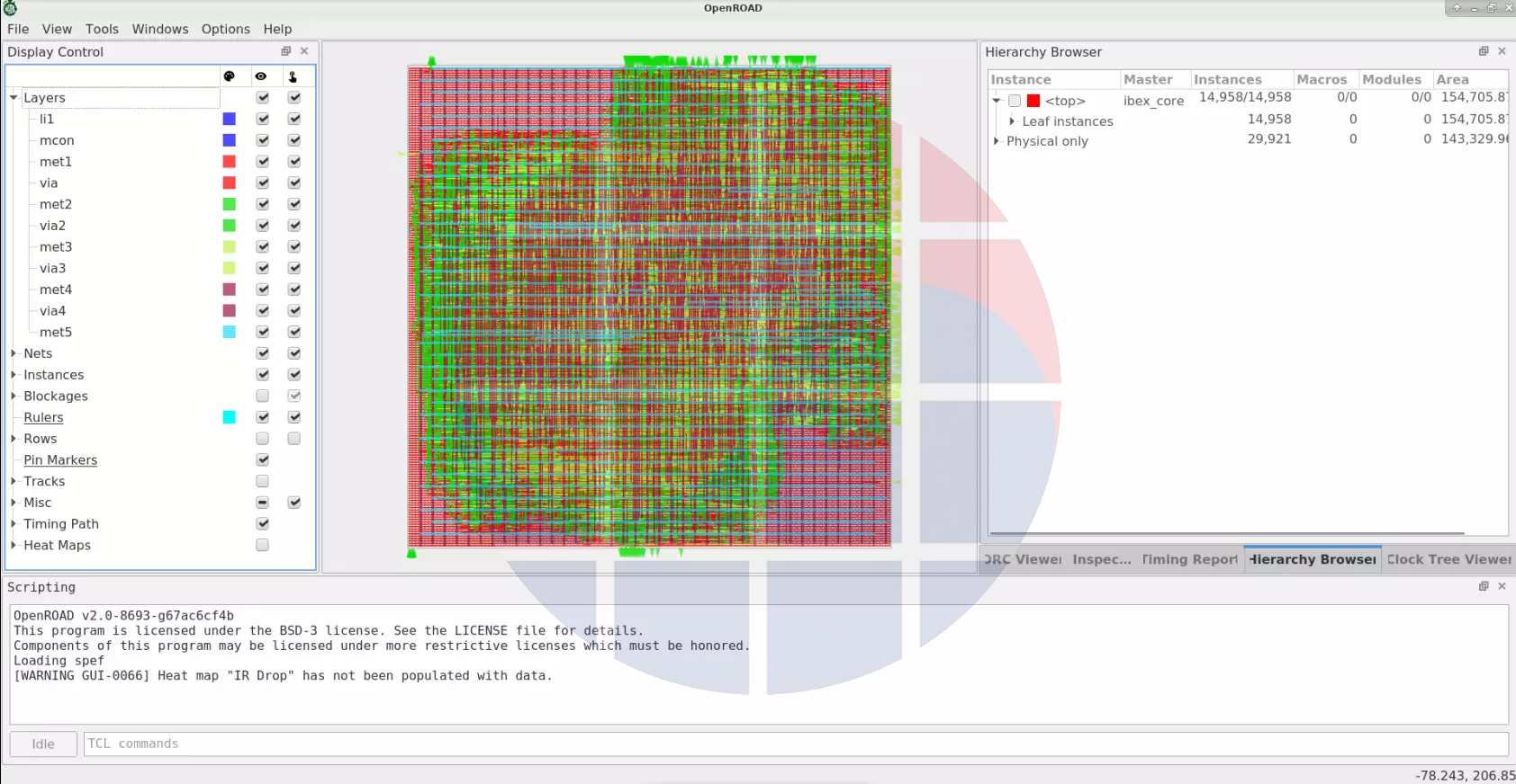
The official Ibex routing screenshot illustrates inspection of layers and connection geometry. Its instance counts and display state differ from the earlier density screenshot, so the images are not a controlled before/after experiment. They illustrate different observation tools.
The layer-resource adjustment described in the global-routing documentation changes how many tracks the router assumes it can use. A better congestion metric after changing that assumption does not mean the physical metal layer acquired more capacity. Detailed routing and extracted results must validate the assumption.
A successful command or cleaner heatmap is not release evidence. Check documentation for the installed revision, run a controlled experiment, and recheck route legality and timing. This article does not invent commercial-tool commands or foundry signoff criteria.
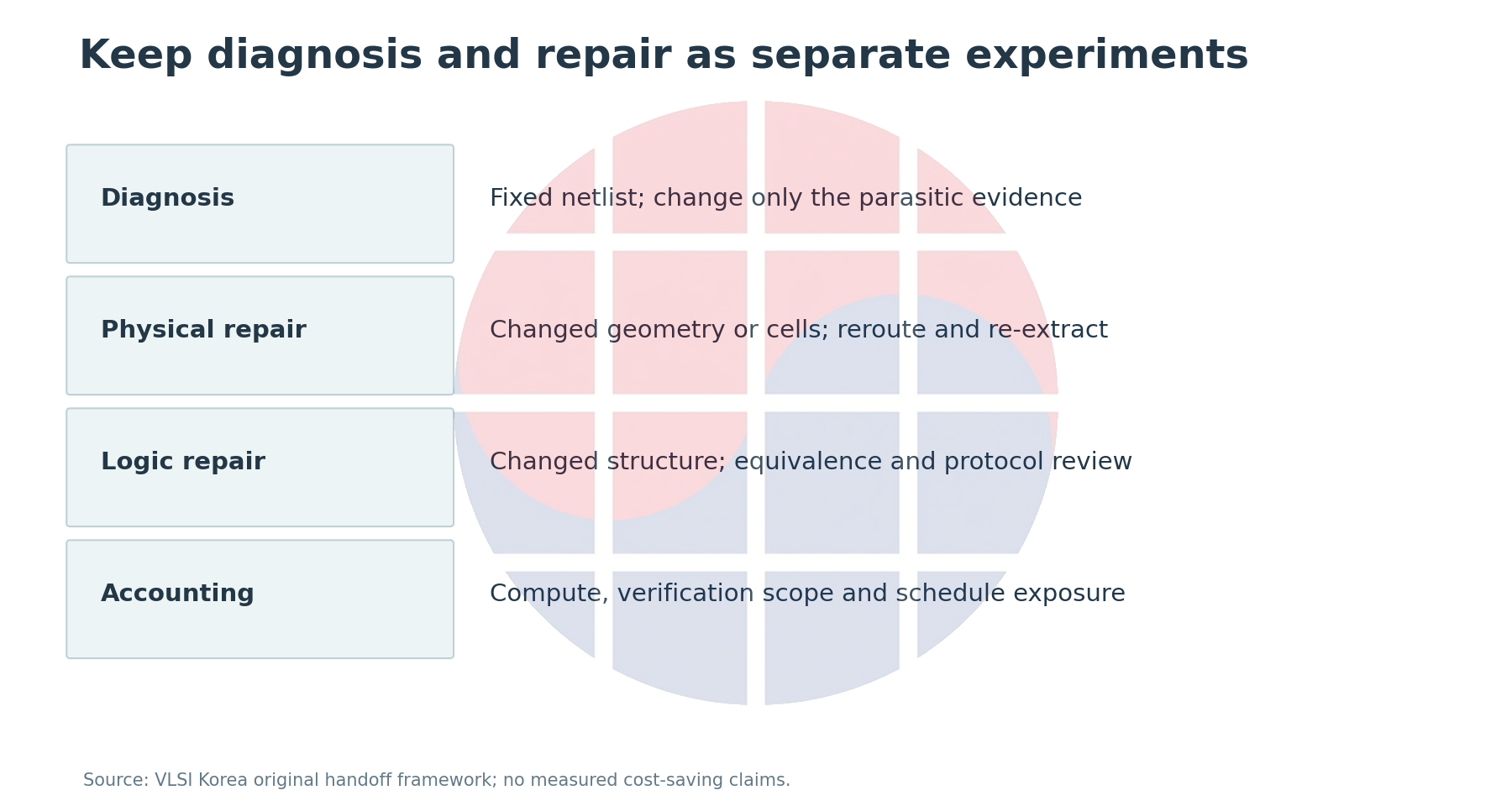
Give the receiving team an actionable question
When RTL, synthesis and PD span organizational or company boundaries, the description of a failure determines the quality of the next experiment. For Korean fabless and design-service teams, identifying what changed under fixed conditions is more useful than naming a process or tool brand.
This does not require exporting a confidential PDK or customer report. Maintain netlist, constraint and deck identities and change ownership within the authorized internal environment. Use permitted abstractions and separate public examples for external discussion. The calculations here are deliberately educational examples.
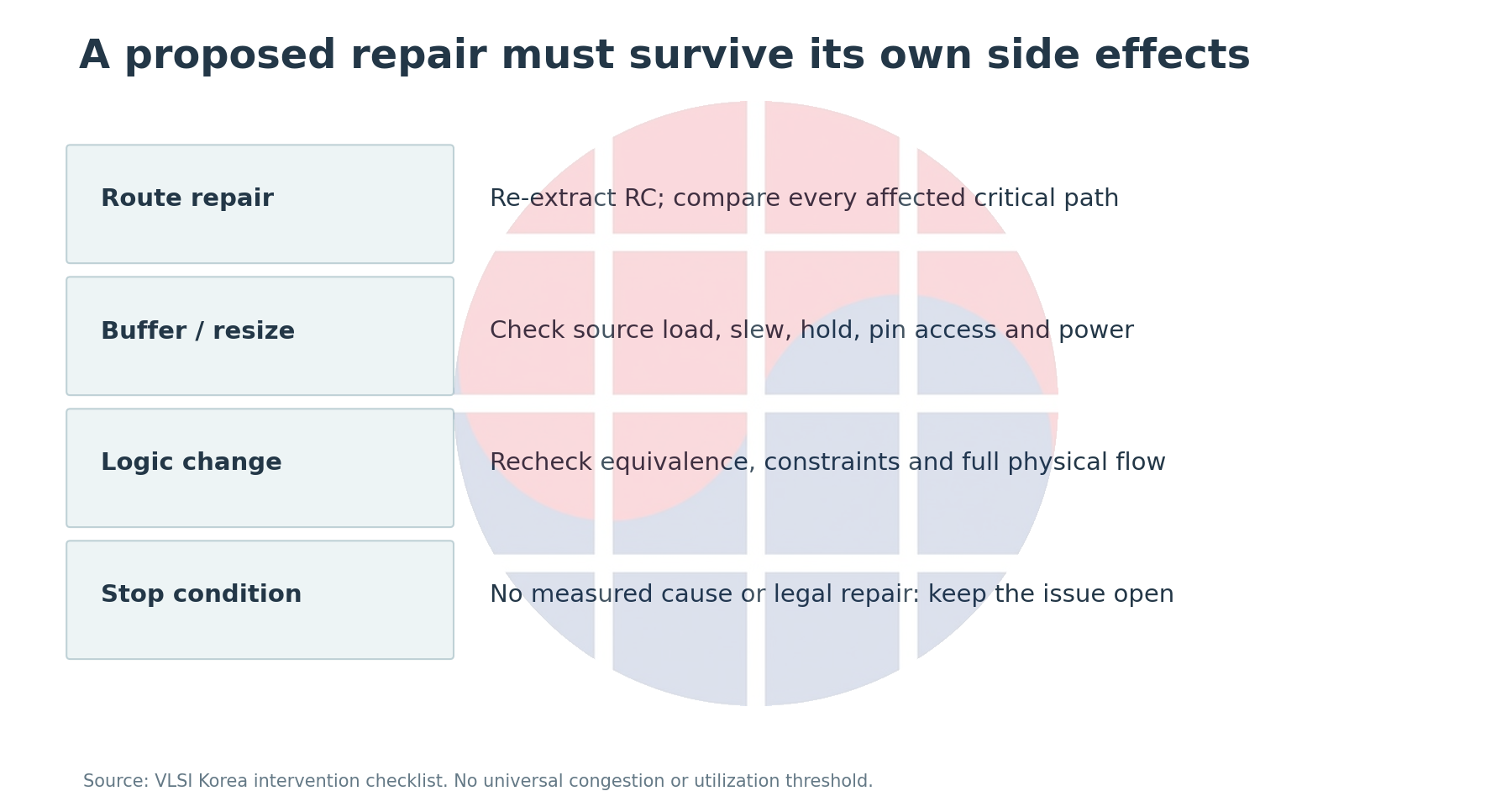
Do not account for cost using ECO count alone. Separate compute time spent repeating the same failure, verification scope added by a modification, signoff reruns and schedule exposure. No observed cost-saving rate or investment return is available here, so no monetary benefit is claimed.
The practitioner checklist is concrete: verify fixed comparison conditions, match the path, quantify the margin explained by RC and the unexplained residual, and identify costs imposed on other paths, hold and routing legality. An unanswered item remains unresolved.
The thesis also has failure conditions. If matched-view RC changes do not explain the timing loss, if a shorter route worsens another critical path, or if library validation materially changes the intrinsic assumptions, discard the original diagnosis and decompose the problem again.
Use 2027-03-07 as an editorial review target for GR/DR residuals by layer and macro distance, 2027-06-07 for hold, pin access and extraction consistency after buffering, and 2027-09-07 for changes in placement or routing interfaces and estimation methods. These are proposed observation dates, not vendor announcements or promises of future improvement.
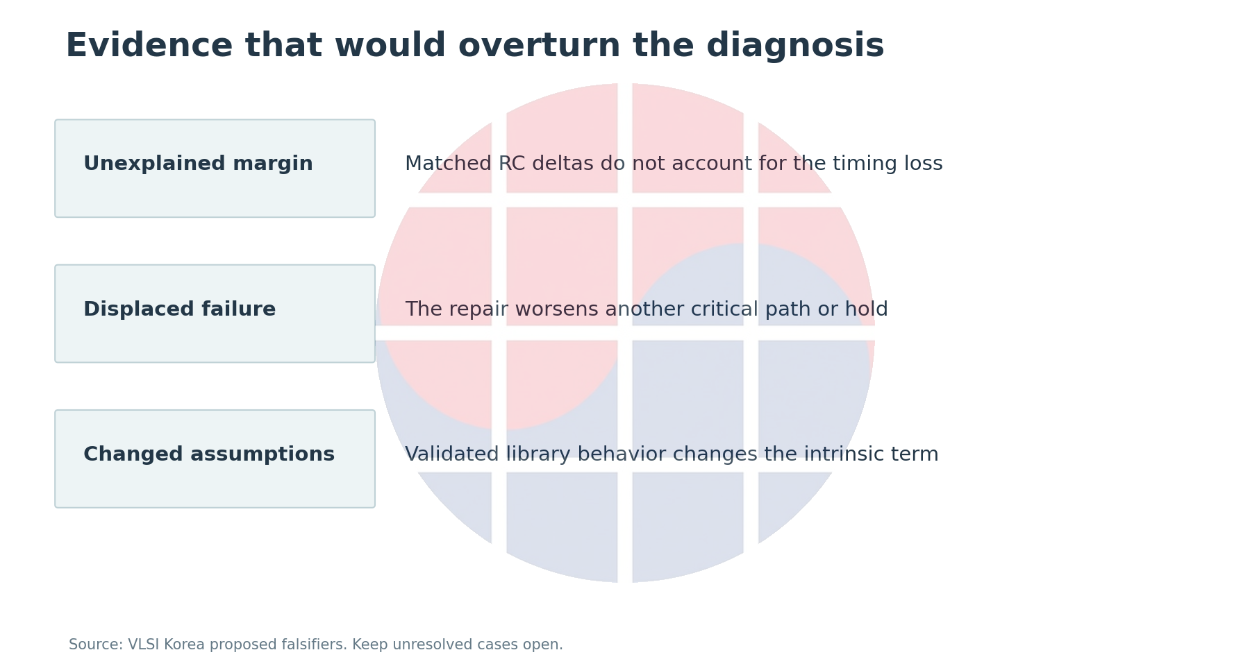
The next handoff should say more than “run it again.” State which identities stay fixed, which delta needs explaining and which intervention will be tested. That turns synthesis-to-PD feedback into a process that removes causes rather than repeats work.
Sources and calculations
Global Placement · Global Routing · Gate Resizer · Parasitics Extraction · A Machine Learning Approach to Improving Timing Consistency between Global Route and Detailed Route · Fast and Accurate Routing Demand Estimation for Efficient Routability-driven Placement · Electrical Timing Issues: The Elmore Delay Model
OpenROAD screenshots: Copyright (c) 2018-2025, The OpenROAD Authors. BSD 3-Clause license. Watermark added; no endorsement.
OpenROAD screenshot license: conditions and disclaimer
BSD 3-Clause License
Copyright (c) 2018-2025, The OpenROAD Authors. All rights reserved.
Redistribution and use in source and binary forms, with or without modification, are permitted provided that the following conditions are met:
1. Redistributions of source code must retain the above copyright notice, this list of conditions and the following disclaimer.
2. Redistributions in binary form must reproduce the above copyright notice, this list of conditions and the following disclaimer in the documentation and/or other materials provided with the distribution.
3. Neither the name of the copyright holder nor the names of its contributors may be used to endorse or promote products derived from this software without specific prior written permission.
THIS SOFTWARE IS PROVIDED BY THE COPYRIGHT HOLDERS AND CONTRIBUTORS "AS IS" AND ANY EXPRESS OR IMPLIED WARRANTIES, INCLUDING, BUT NOT LIMITED TO, THE IMPLIED WARRANTIES OF MERCHANTABILITY AND FITNESS FOR A PARTICULAR PURPOSE ARE DISCLAIMED. IN NO EVENT SHALL THE COPYRIGHT HOLDER OR CONTRIBUTORS BE LIABLE FOR ANY DIRECT, INDIRECT, INCIDENTAL, SPECIAL, EXEMPLARY, OR CONSEQUENTIAL DAMAGES (INCLUDING, BUT NOT LIMITED TO, PROCUREMENT OF SUBSTITUTE GOODS OR SERVICES; LOSS OF USE, DATA, OR PROFITS; OR BUSINESS INTERRUPTION) HOWEVER CAUSED AND ON ANY THEORY OF LIABILITY, WHETHER IN CONTRACT, STRICT LIABILITY, OR TORT (INCLUDING NEGLIGENCE OR OTHERWISE) ARISING IN ANY WAY OUT OF THE USE OF THIS SOFTWARE, EVEN IF ADVISED OF THE POSSIBILITY OF SUCH DAMAGE.
AI assisted source organization, writing and diagram production. The article received independent factual review. Calculations are reproducible examples under declared assumptions, not benchmarks of a real design or commercial tool.