VLSI Korea
Can a terrestrial data-center GPU go straight into space?
Separate chip reuse from board and spacecraft redesign using H100, Suncatcher and Space-1 evidence, then size accelerators and power for equal completed work.


A terrestrial GPU can operate in space. The engineering task is to separate reusable compute silicon from the power, cooling and recovery systems that must be designed around it. Running the same software does not establish that the same server configuration will sustain the same throughput throughout a mission.
As of 2026-10-06, Google has announced the launch and confirmed contact with its Suncatcher prototype, developed with Planet, on 2026-10-01. The question is moving from launch feasibility to operating evidence. Google's announcement says the team will collect data on TPU behavior under radiation and thermal conditions.
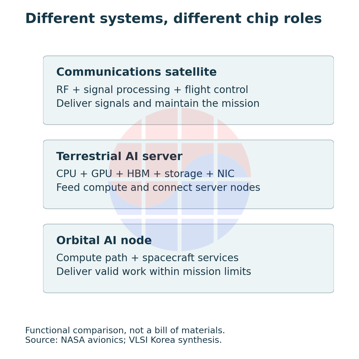
VLSI Korea view: Draw the reuse boundary before comparing space AI chips. A module that can be purchased, a module that can be integrated into a spacecraft, and a system that continually produces valid results are different acceptance targets.
This article serves engineers defining accelerator-board changes and readers evaluating orbital-compute proposals. It focuses on two decisions: which components can remain unchanged, and how much power and hardware must be allocated to deliver the same completed workload.
1. Communications satellites and AI servers assign different jobs to chips
A communications satellite receives and transmits radio signals while managing communications paths, attitude and power. RF front ends, signal-processing ASICs or FPGAs, and control MCUs perform different work from the repeated matrix operations assigned to GPUs and TPUs. Adding an AI accelerator does not remove communications or flight-control responsibilities.
In a terrestrial AI server, the CPU prepares programs and data while the GPU performs parallel computation. HBM supplies bandwidth close to the accelerator; host DRAM and SSDs serve different capacity, latency and persistence requirements. NICs and switches move data between servers. This data path matters before the component list does.
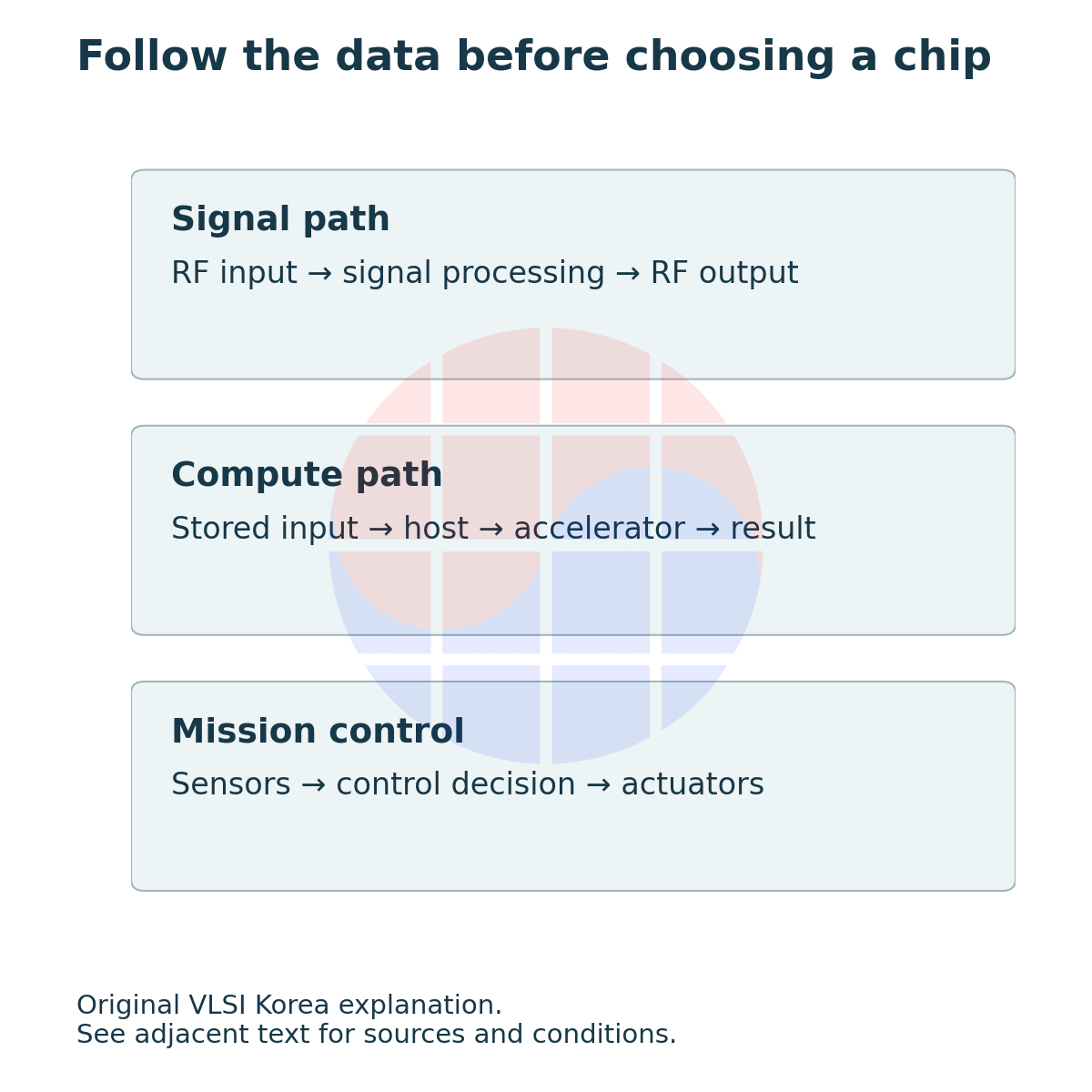
An orbital AI node combines that compute path with spacecraft functions. Image classification whose results can wait for transmission has different failure conditions from a decision needed immediately for attitude control. Even with the same GPU, latency limits, output validation and restart policies can differ.
NASA's small-spacecraft avionics chapter likewise describes processor and architectural choices in terms of mission throughput, power and real-time requirements. A processor's compute rating alone is a poor measure of an entire spacecraft's maturity.
SpaceX-related systems also need separate identities. NVIDIA's 2026-08-24 announcement names an optimized Vera Rubin NVL72 for SpaceXAI's planned Starmind satellite. That is neither a Starlink communications-satellite bill of materials nor an announcement that an unchanged terrestrial rack has flown.
2. Keeping the die does not preserve every module and cluster requirement
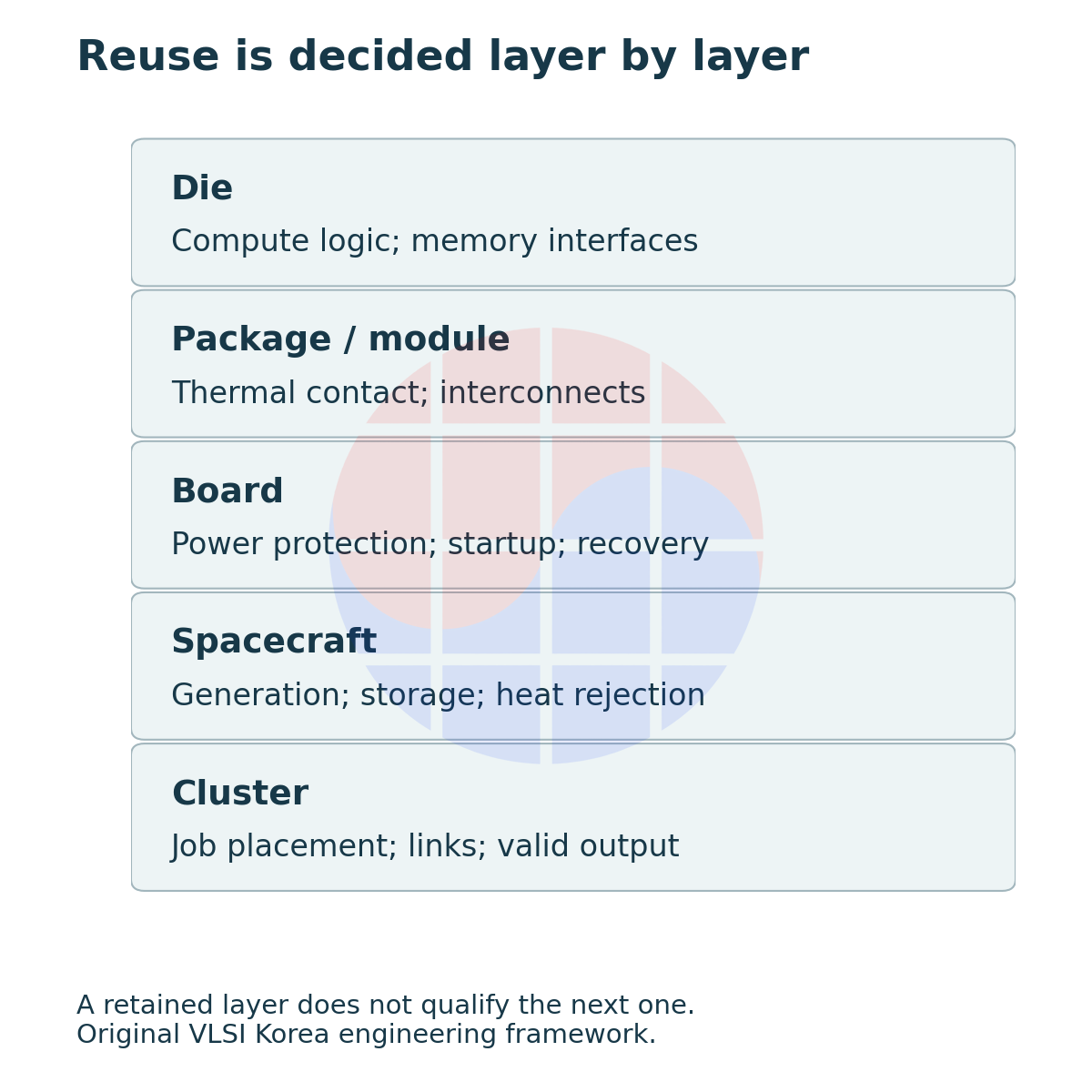
The die contains compute logic and memory interfaces. The package connects the die to external circuitry and carries heat away. Modules and boards add power conversion, connectors and management circuits. The spacecraft combines these with generation, storage, heat rejection and attitude control; a cluster coordinates communications and job placement across nodes.
An unchanged layer does not eliminate testing at the next layer. The same die attached to a different cooling interface or mechanical support can experience different temperature distributions and load paths. Changing a board's current-limiting device also requires checking how its settings distinguish normal startup from a fault.
NVIDIA's H100 PCIe product brief, PB-11133-001_v02, specifies a maximum 350 W configuration and 80 GB of HBM2e. Its passive heatsink depends on airflow supplied by the server. The current H100 SXM specification instead lists a configurable maximum of 700 W. Treating both as the same “one H100” input changes the starting conditions of a calculation. PCIe brief, SXM specifications
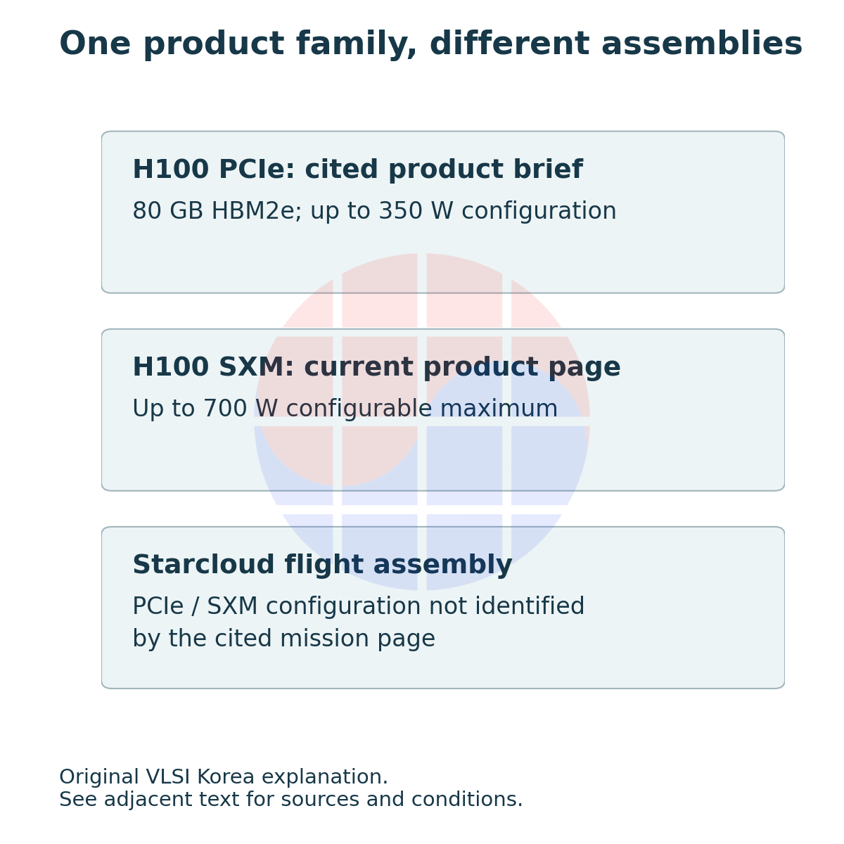
Starcloud's mission page describes an H100 launch in 2025-11 and a nanoGPT training demonstration in 2025-12. It does not disclose the flight assembly's PCIe or SXM configuration or a complete bill of materials. The terrestrial PCIe photograph and specifications in this article therefore do not identify that satellite's actual board.
An interface document can make reuse concrete: retain a driver or instruction set, modify mechanical, power and thermal interfaces, and retest startup and recovery paths. COTS means commercial off-the-shelf procurement. It is not a mission-suitability verdict.
3. What comes after demonstrating that a computer works in orbit?
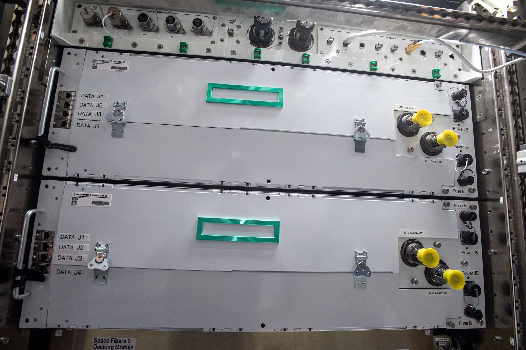
On 2024-01-30, HPE announced that a new configuration of its commercial-server-based Spaceborne Computer had been sent to the ISS. The photograph here shows the earlier Spaceborne Computer-2 on 2021-04-29. Computing inside the ISS is useful evidence, but it does not establish the power and cooling design of a free-flying satellite exposed to external vacuum. HPE announcement
“Worked” needs a test scope. Successful boot, an application running for a bounded period, recovery after a fault, and stable service across multiple nodes are separate observations. Each provides a starting point for the next test; it does not produce performance evidence for unobserved behavior.
Google's published tests illustrate the distinction. Its 2025 research exposed Trillium v6e to 67 MeV protons and reported HBM-test irregularities after a cumulative 2 krad(Si). No permanent failure was attributed to TID up to the maximum tested dose of 15 krad(Si) on a single chip. Google Research
Those values belong to the tested components and conditions. Section 2.3 of the research preprint v1 describes an environment using 10 mm aluminum-equivalent shielding as an example and a 5-year reference dose of 750 rad(Si). These results alone do not determine the lifetime of another accelerator, another shielding configuration or a complete spacecraft.
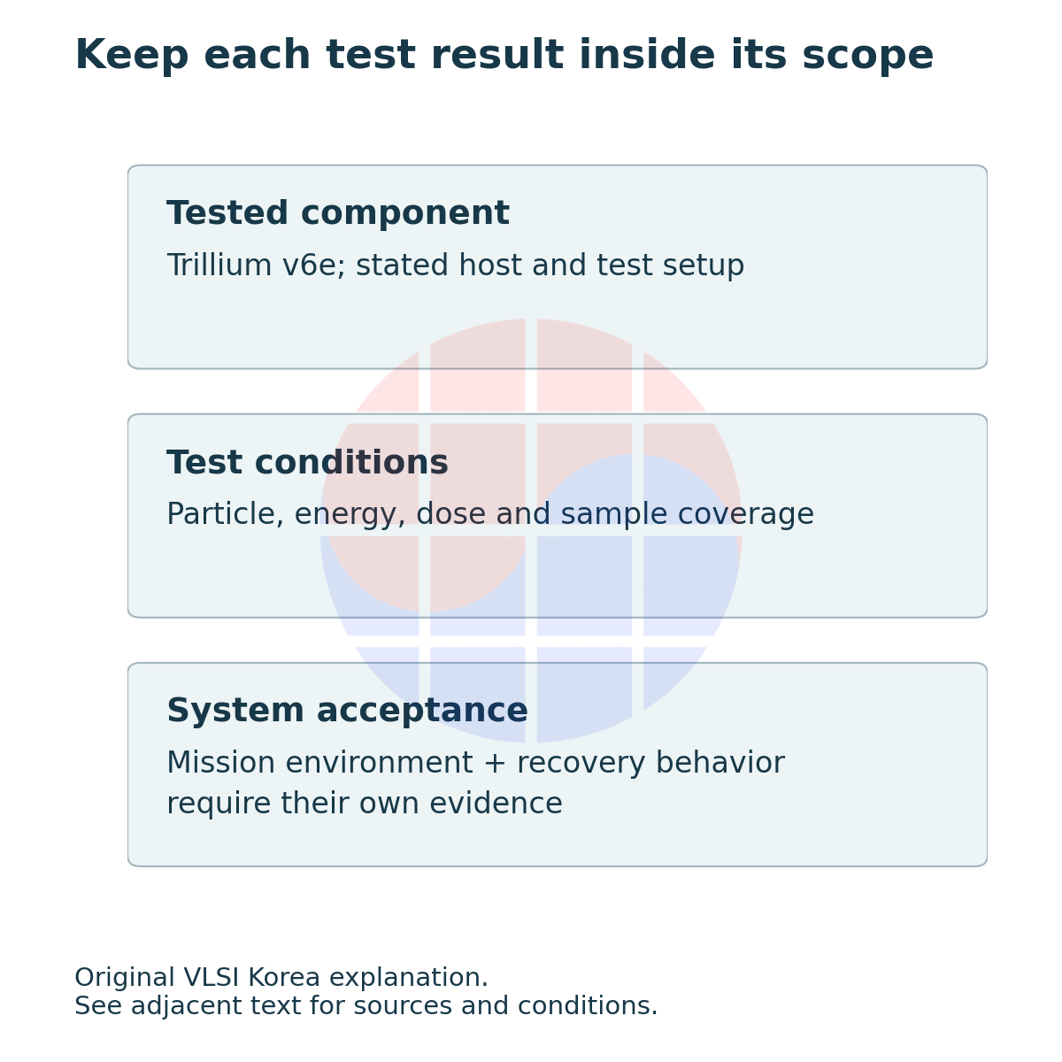
Total ionizing dose, or TID, differs from displacement damage to a crystal lattice and from single-event effects triggered by an individual particle. An upset in a logic state and latch-up that sustains abnormal current cannot be treated as the same recovery problem.
ECC detects or corrects defined error patterns. It neither interrupts latch-up current nor detects every computational error. A design review should place error-detection points, responsibility for power interruption and conditions for trusting recovered output beside the “ECC supported” entry. The existing LEO memory reliability reference develops scrubbing and checkpoint design in more detail.
4. Where does the GPU's consumed power eventually go?
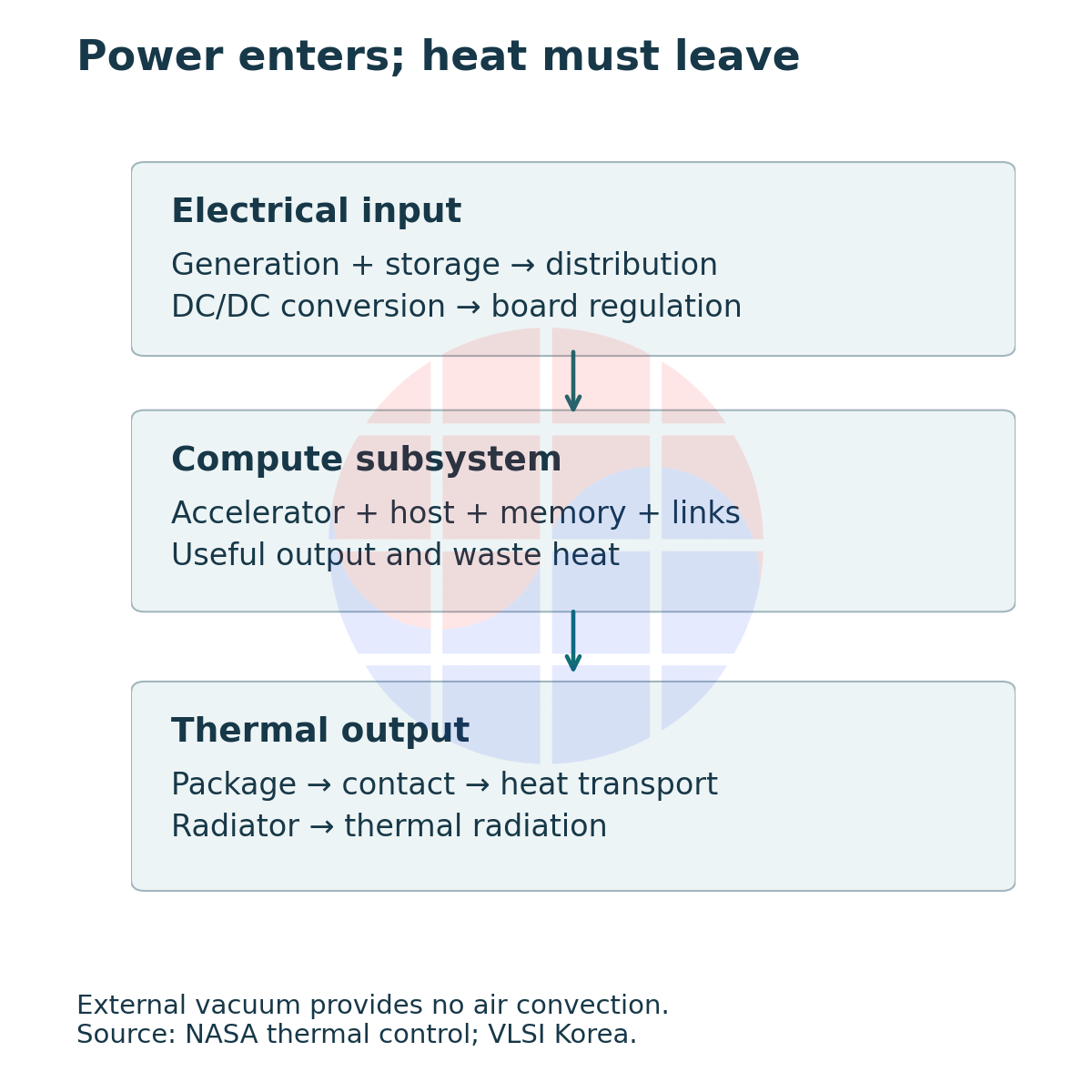
Vacuum provides no convection path to external air. Heat must travel through the package, contact interfaces and thermal transport hardware before a radiating surface rejects it. NASA's thermal-control chapter distinguishes internal conduction from external radiation. A cold space background alone does not determine GPU junction temperature.
A cold plate validated on Earth does not automatically encounter the same conditions in a spacecraft. Contact thermal resistance, pipes and pumps, fluid operating limits, and the temperature difference to the final radiator must be designed together. Keeping the accelerator cooler can change the margin and mass required at the heat-rejection end.
Power does not flow directly from a solar array into the GPU either. Storage, distribution, DC/DC conversion and board voltage regulation contribute to power and thermal budgets. The separation between an accelerator's startup load and spacecraft communications or control power also needs verification.
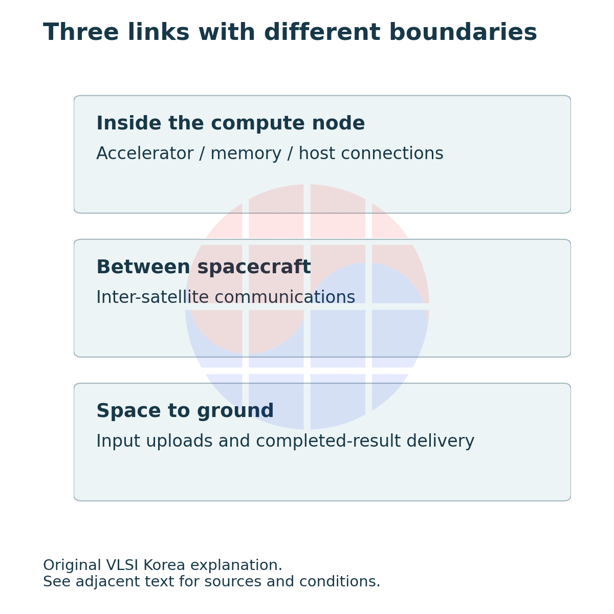
The design choice is broader than a larger radiator. A team might cap sustained performance, schedule work across fewer simultaneously active accelerators, or change mechanical and thermal interfaces. These choices affect completion time more directly than a nominal compute rating does.
Communications add another layer. Short electrical links between accelerators, optical links between spacecraft and links carrying results to the ground have different latency, bandwidth and availability. To preserve a model's terrestrial scaling efficiency, first measure where jobs wait and how much data they move.
Extracting useful information from imagery generated in orbit and uploading a large terrestrial dataset for distributed training begin with different data-flow directions. Identical chip specifications can therefore produce different mission value. A mission-specific processing path is more useful than a single ranking of “space GPUs.”
5. Compare completed work, not just installed accelerator count
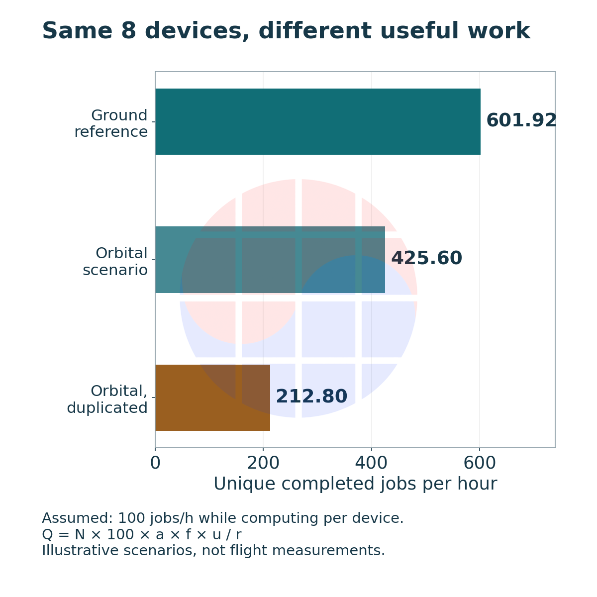
The following design example uses assumed inputs, not measurements of a product or orbit. For a workload with identical input, precision and correctness requirements, assume 1 accelerator completes 100 jobs per hour while computing. Separate installed count N, online fraction a, the fraction f of online time that is not blocked by communications, and the compute-allocation fraction u within that remaining time.
If each job runs simultaneously on r devices for result comparison, unique completed throughput Q is N × 100 × a × f × u ÷ r. Here r counts active duplicate execution. The expression does not directly describe powered-off spares or checking only a subset of jobs.
For the r=2 scenario, a, f and u are conditional readiness fractions for a complete two-device execution group, not independent per-device fractions. They do not calculate the reliability of pairing independently available devices.
The denominators must not overlap. If GPU utilization already includes communications stalls, using it for u and multiplying by f again deducts the same loss twice. Keep the conditional definitions: a is online time, f is communications readiness within it, and u is compute allocation within the remaining interval.
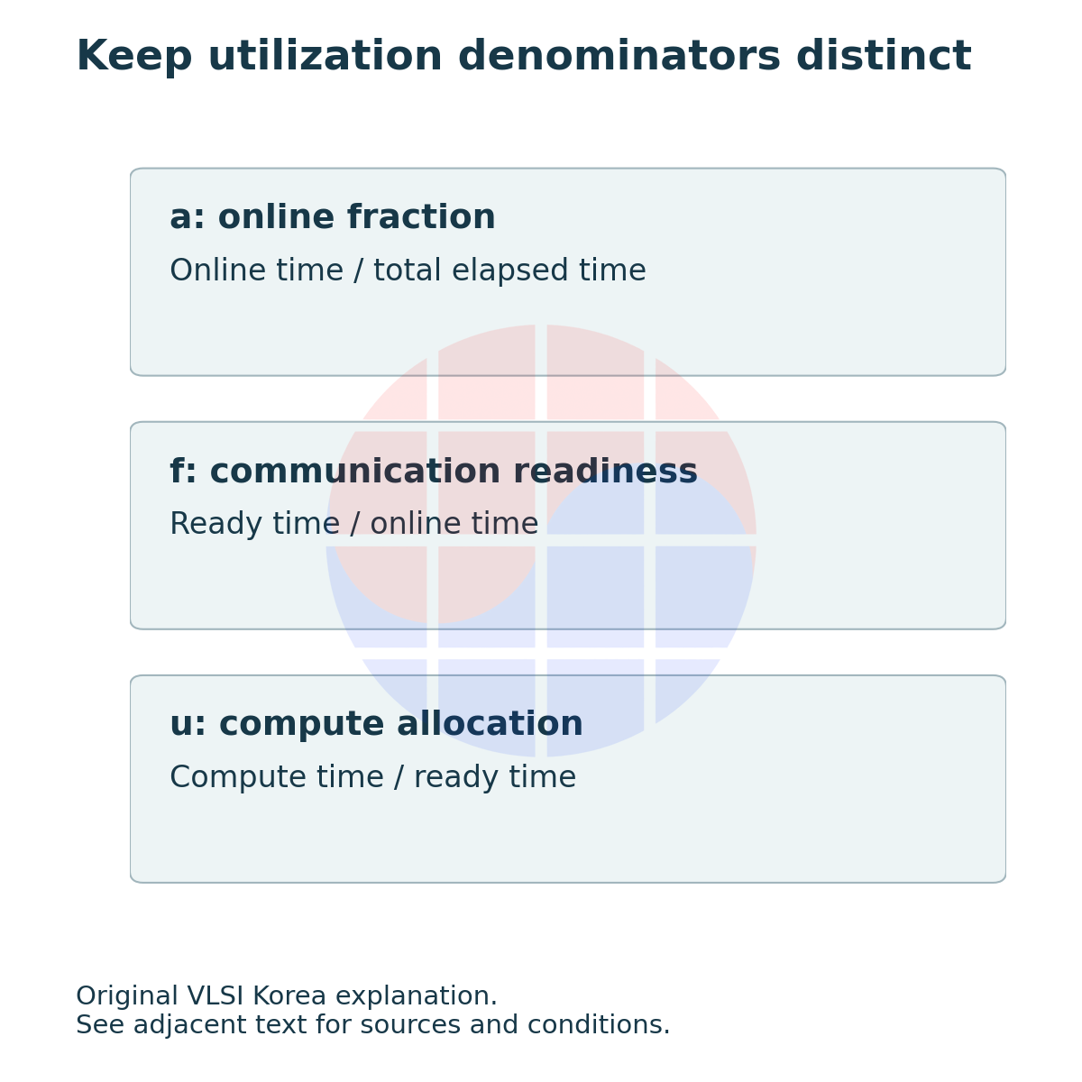
The terrestrial reference assumes a=0.99, f=0.95, u=0.80 and r=1. The orbital scenario assumes a=0.95, f=0.80, u=0.70 and r=1. With the same 8 installed devices, Q is respectively 601.92 and 425.60 jobs per hour. This is the consequence of assumed operating conditions, not a measured disadvantage of orbital hardware.
Running every orbital job on 2 devices changes r to 2 and Q to 212.80 jobs per hour. The example does not calculate any reliability improvement from duplication. Detecting disagreement, choosing the correct result and avoiding common-cause faults remain separate design questions.
VLSI Korea view: Reliability features do not provide free performance. Explain the cost of performing the same computation twice separately from what the system can do when it discovers an error.
If communications stalls cause the reduction, a faster GPU alone is insufficient. Consider better placement of independent jobs or overlapping transfers with computation. Conversely, if a workload does not fit in memory, assuming a higher allocation fraction for that same workload is already invalid.
6. Matching throughput reveals costs beyond the board
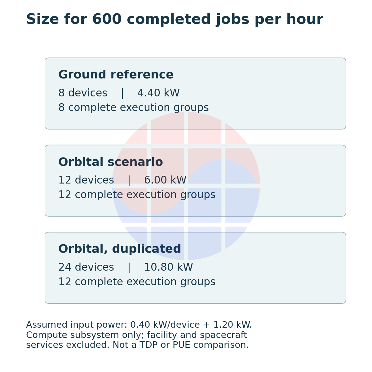
At a target of 600 jobs per hour, the terrestrial reference needs 8 devices and the orbital scenario needs 12. Running every job on 2 devices requires 12 groups, or 24 devices. Round up complete execution groups rather than calculating a fractional device count and rounding to the nearest integer.
Use a consistent power boundary as well. Assume average power of 0.40 kW per device plus a fixed 1.20 kW for the host, memory, communications and conversion losses. Compute-subsystem input power becomes 4.40 kW, 6.00 kW and 10.80 kW respectively. These are not measurements obtained by substituting an H100 TDP.
This boundary excludes terrestrial facility cooling and the complete spacecraft attitude-control, propulsion, solar-generation and storage systems. The values are inputs to a cost comparison, not a comparison of terrestrial and orbital electricity bills or PUE. Treating host and network power as fixed while load increases is another simplification that a real design must remove.
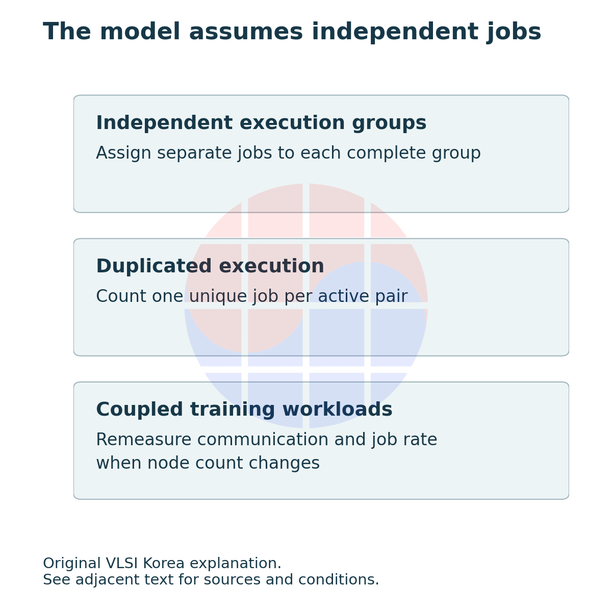
Installing 12 devices cannot meet the target if current delivery or heat transport remains sized for 8. If a power cap reduces each device's job rate, the initial 100-jobs-per-hour assumption must be measured again. Adding devices and adding usable system capacity are different events.
Scaling also has a boundary condition. This calculation distributes independent jobs across groups. A training job that frequently gathers results across nodes may have a communications-readiness fraction f that changes with node count. Copying a value measured at 8 devices to 24 can conceal scaling losses.
An economic evaluation must go further: connect completed work over the mission lifetime to launch, shielding, heat transport, radiators, generation, storage, ground stations and replacement. Updating software and replacing a failed board are different lifetime-management options. A single launch-price assumption or product-release year cannot fix the break-even point.
7. Korean suppliers need integration evidence, not just product names
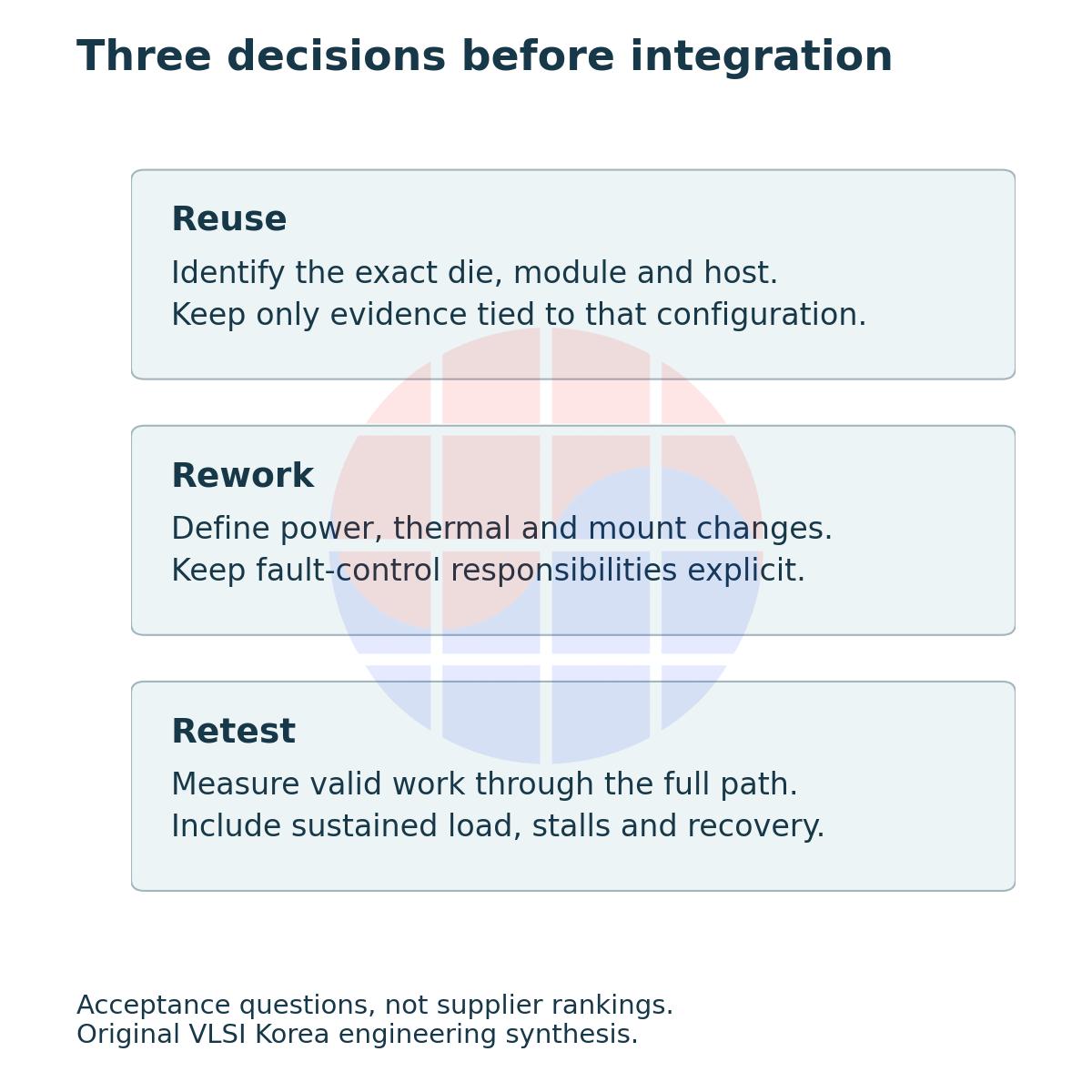
Memory, packaging, board and power teams each have an acceptance question. Memory needs component-specific error observations under stated conditions; packaging needs mechanical and thermal-interface durability; power needs fault isolation and restart sequencing. These are technical participation requirements, not a list of confirmed supplier contracts or revenue.
A purchasing review should first establish whether the candidate is a die, module or complete node. Then link the normal performance sheet to the exact configuration in the mission test report. If the HBM type, power cap, firmware or host changes, agree with the supplier which results remain reusable.
NVIDIA's 2026-03-16 Space-1 announcement points toward integrated CPU-GPU modules for orbital computing. Its availability statement at the time was for a later date, and its up-to-25-times AI-compute comparison is a vendor claim. It is not orbital throughput measured at matched precision and power.
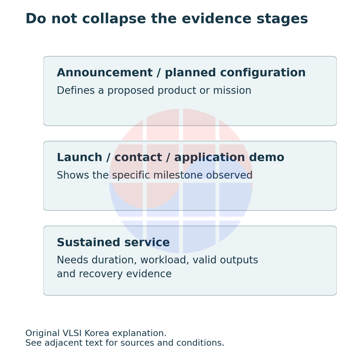
The counterargument is concrete. A short mission with independent jobs and sufficient thermal, power and recovery margins may justify keeping commercial silicon instead of developing a new die. When unrecoverable common-cause faults or missed processing deadlines dominate, high peak performance cannot justify the selection.
Over the next 6-12 months, watch more than launch counts: Suncatcher's environmental results, accelerator and memory error-and-recovery logs, power and temperature under sustained load, and completed work when links stall. VLSI Korea's next review dates are 2027-04-06 and 2027-10-06; they are not vendor release commitments.
A terrestrial GPU can go into space, but contracts and tests must define what “unchanged” covers. Reuse of the chip is a starting point. The next engineering step is to compare power, heat, communications and recovery paths through to valid output under the same workload conditions.
Sources and evidence boundaries
The evidence cutoff is 2026-10-06. Links in the body lead to manufacturers, mission operators, NASA and original research. Launch, contact and demonstration claims are attributed to their publishers; undisclosed flight SKUs and long-term commercial availability are not estimated. The radiation values belong to the stated 2025 tests, not qualification of the newly launched spacecraft as a whole.
Part 1, separating public SpaceX and Starlink chip evidence, addresses adoption evidence. LEO memory reliability develops data repair and state recovery. This article's original diagrams and calculations address system changes and sizing for equal completed work.
AI assisted public-source research, drafting and original diagram production. All scenario inputs are illustrative assumptions, not product or mission benchmarks.
Disclosure
This article is provided for informational purposes only and does not constitute a recommendation to buy or sell any security. Figures and factual statements are based on publicly available sources, including company filings, news reports, and market research, and may contain errors in the source material or in the preparation of this article. The author may own shares in companies mentioned. All investment decisions and their outcomes are the reader's responsibility.