
1. Introduction: Engineering that mathematically and logically proves design intent
From the perspective of the grand flow of semiconductor design—the RTL to GDSII Flow—we have undergone a process of correcting the structural integrity and syntactic errors of the code through Verilog Coding Style and Linting to correct structural soundness and syntactic errors in the code.
Now we enter the realm of Design Verification, the heart of the design and the stage consuming the most time and resources.
Verification is not merely a testing process to confirm whether the RTL code "runs." It is the process of proving that the Architecture Specification intended by the designer has been accurately translated into the RTL implementationand proving that there will be no logical issues in subsequent stages like Logic Synthesis.
In modern SoC (System on Chip) design, Verification carries such significant weight that it often consumes more time than the RTL design phase itself. This is a critically important phase because the cost of fixing bugs discovered after chip fabrication (silicon bugs) can be thousands of times higher than fixing them at the RTL stage. Consequently, there is a tremendous demand for professionals in this field.content/images/2026/01/image-50.png" class="kg-image" alt="" loading="lazy" width="750" height="677" srcset="https://www.vlsi.kr/content/images/size/w600/2026/01/image-50.png 600w, https://www.vlsi.kr/content/images/2026/01/image-50.png 750w" sizes="(min-width: 720px) 720px">
Therefore, the goal of a Verification Engineer goes beyond simply finding bugs; it is to provide statistical and logical evidence that "there are no bugs."
2. Paradigm Shift in Verification Methodology: From Directed to Constrained Random
Decades ago, when verifying designs with hundreds of gates, the predominant approach was Directed Testing, where engineers manually coded each predictable scenario. However, relying solely on human prediction is nearly impossible for modern designs with VLSI-scale complexity. This limitation has fundamentally changed the verification methodology.fundamental shift in verification theory.EA%B4%80%EC%A0%81%EC%9D%B4%EC%A7%80%EB%A7%8C-%ED%95%9C%EA%B3%84%EA%B0%80-%EB%AA%85%ED%99%95%ED%95%9C-%EC%A0%91%EA%B7%BC">2.1 Directed Testing: An Intuitive Approach with Clear Limitations
Directed Testing is a method where the verification engineer explicitly defines the Stimulus input and Expected Output to verify whether a Feature functions correctly. For example, in processor verification, a test like "Execute instruction B after instruction A and verify that the register value is C" falls under this category.
The advantages of this approach are clear. The test intent is explicit, making debugging easier and enabling quick verification of basic functionality during the initial bring-up phase.
However, the critical drawback is it absolutely cannot verify "scenarios the engineer didn't consider." Complex pipeline stalls, race conditions between asynchronous interfaces, and handling exceptional errors are difficult for the human mind to enumerate all possible combinations. Furthermore, every time the design specification changes, the manually written test cases must be individually modified, causing maintenance costs to increase exponentially.
2.2 Constrained Random Verification (CRV)
To overcome these limitations of Directed Testing, Constrained Random Verification (CRV) emerged.
CRV leverages SystemVerilog's object-oriented programming capabilities and randomization features to generating testbenches that explore the state space randomly while imposing constraints within valid ranges for verification.
The core of CRV is randomness, automation, and exploration.
Instead of writing individual test vectors, engineers define only the structure of the data packet and the protocol rules (constraints). Each time the simulator calls the `randomize()` function, it generates a different combination of data, addresses, delays, and control signals. For example, constraints like `constraint valid_addr { addr < 1024; } ensures random access attempts occur within the valid address space.
The simulator generates complex scenarios that humans might overlook, such as corner cases like "a situation where a FIFO is full, a reset suddenly occurs, and an interrupt happens simultaneously."
3. UVM (Universal Verification Methodology)
Implementing CRV effectively requires a robust and reusable framework. This is precisely why UVM (Universal Verification Methodology) was created and has become the current industry standard.
Many junior engineers become frustrated when faced with UVM's complex class hierarchy and vast array of macros. However, once you understand the purpose and role of each component, you'll see that UVM has a very logical structure.
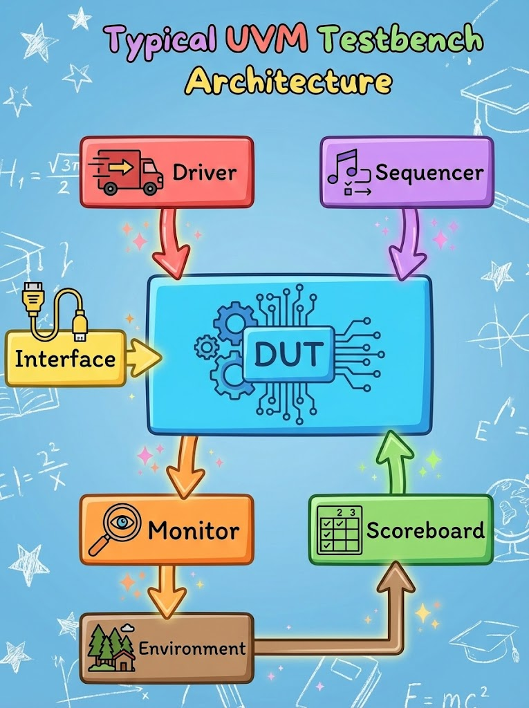
3.1 The Philosophy of the UVM Testbench: Separation of Concerns
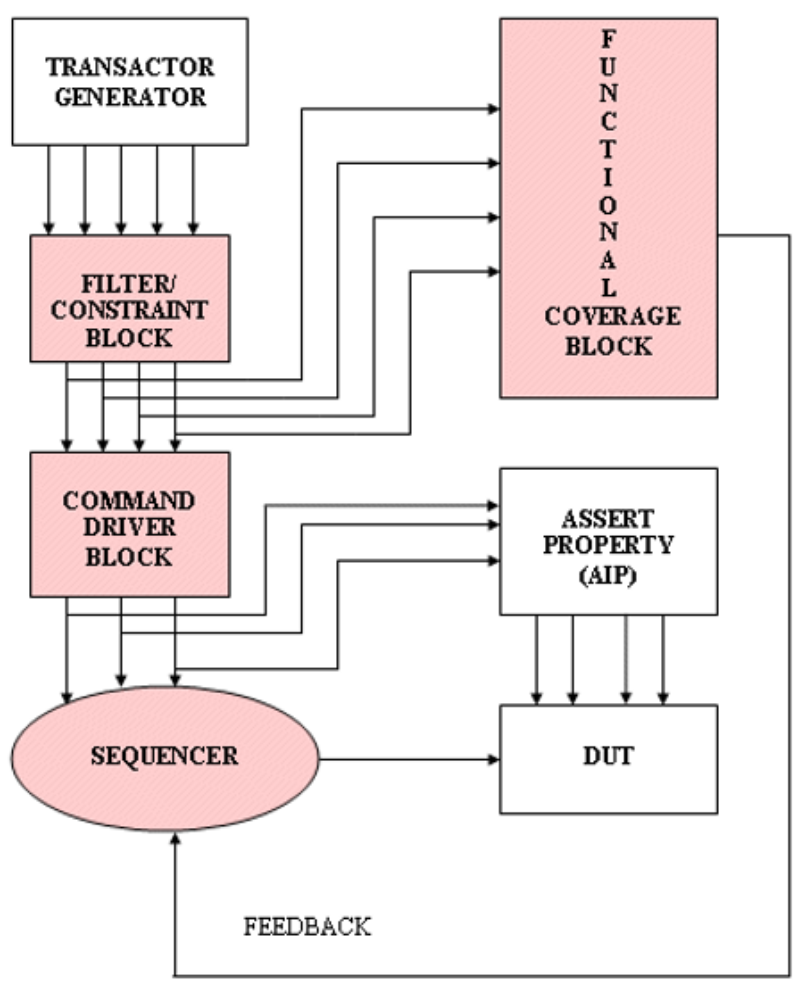
The core philosophy of UVM is to thoroughly modularize the verification environment by function. That is, the roles of Stimulus Generation, Signal Driving, Signal Monitoring, and Answer Verification are separated into distinct components. This approach ensures that when a verification environment is created for a specific protocol (e.g., PCIe), it can be easily reused in other projects, achieving high reusability.
3.2 Detailed Analysis of Core Components
3.2.1 Sequence Item (Transaction): The Beginning of Abstraction
The most fundamental unit of verification is the uvm.sequence_item transaction.EC%8B%9C%EC%9E%91">3.2.1 Sequence Item (Transaction): The Beginning of Abstraction
The most fundamental unit of verification is the uvm_sequence_item. This object abstracts signals (0s and 1s) at the pin level into 'Transactions', which are meaningful chunks of information. For example, While numerous control signals flow on the AXI bus, at the Transaction level, they are represented solely by attributes such as Address, Data, Read/Write, and Burst Length. This allows verification engineers to focus on the data flow itself, freeing them from complex timing considerations.
3.2.2 Sequencer: The Control Tower of Data Flow
uvm_sequencer acts as an intermediary, passing generated Sequence Items to the Driver. Beyond simply transferring data, it performs arbitration—deciding which Sequence's Item to send first when multiple Sequences run concurrently. For example, when a regular data transfer Sequence and an urgent interrupt Sequence run simultaneously, the Sequencercan send the interrupt-related item to the Driver first based on priority settings. This concept is analogous to the bus arbiter in actual hardware.
EC%9D%98-%EA%B5%90%EB%9F%89">3.2.3 Driver: The Bridge Between Abstraction and Reality
uvm_driver converts the abstract transaction packets received from the Sequencer into pin-level signals that the actual DUT (Design Under Test) can understand. The TLM (Transaction Level Modeling) interface is used in this process. The Driverrequests Items via seq_item_port.get_next_item(req) to request items and controls the virtual interface through internal logic to toggle signals on clock edges. The Driver is solely involved in 'inputs' and does not evaluate or inspect output data from the DUT. This is strictly the responsibility of the Monitor and Scoreboard.
3.2.4 Monitor: The Eye of Verification (Observer)
uvm_monitor is a component that passively observes (Passive Monitoring)It does not apply any signals to the DUT, but only detects signal changes through the virtual interface. The Monitor detects changes in signals at the pin level and reassembles them into transaction form (uvm_sequence_item). This reassembled information is broadcast to subscribers such as the Scoreboard or Coverage Collector via the analysis_port(Subscriber). Additionally, the Monitor may include an Assertion Checker to verify basic protocol compliance.EC%9D%98-%EC%BA%A1%EC%8A%90%ED%99%94">3.2.5 Agent: Protocol Encapsulation
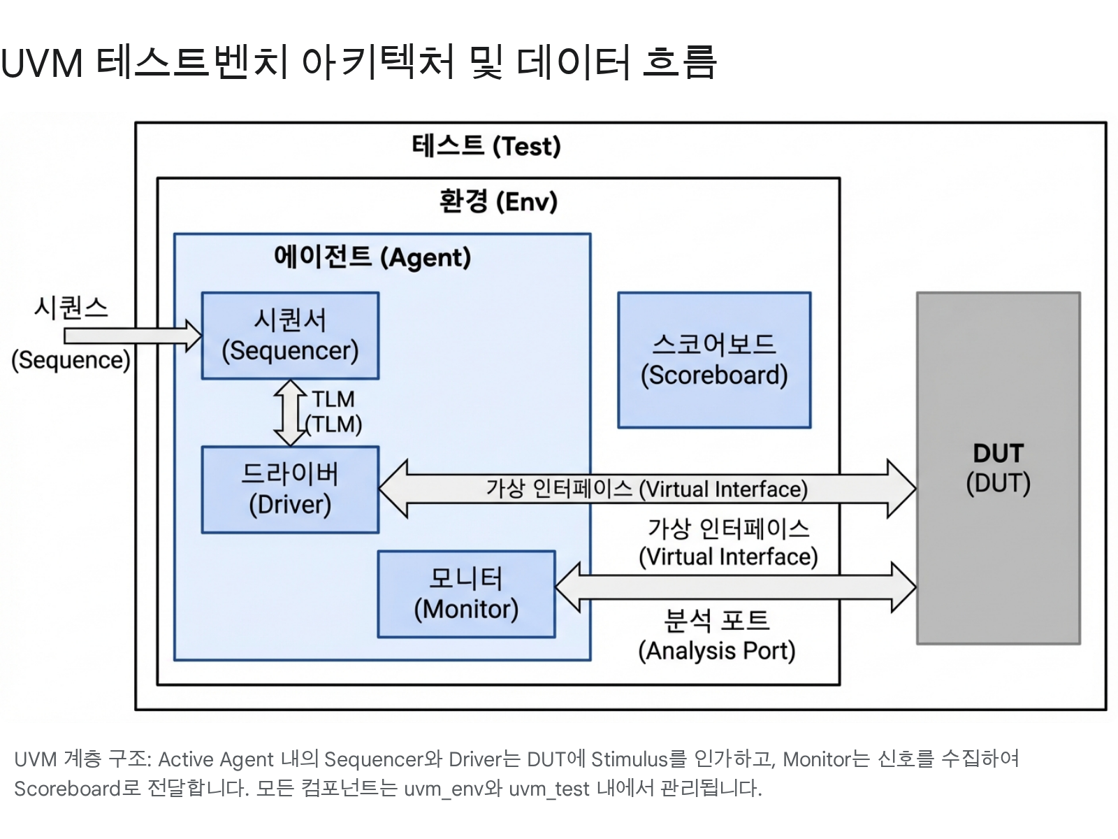
uvm_agent is a container that bundles the Sequencer, Driver, and Monitor described above. The Agent becomes a unit of the verification IP (VIP) that handles specific interface protocols (e.g., AXI, UART). AXI, UART). The Agent serves as the unit for verification IP (VIP) handling a specific interface protocol. The Agent operates in two modes based on a configuration variable called `is_active`:
- Active Mode: Creates both a Sequencer and a Driver to actively apply Stimulus to the DUT.
- Passive Mode: Creates only a Monitor to observe bus signals. This is used for verifying subsystems within the chip or for system monitoring when another master is already driving the bus.
3.2.6 Scoreboard: Judge (Checker)
uvm_scoreboard is the core component for determining Pass/Fail in verification. It compares the actual output collected from the Monitor (Actual Output) with the expected output(Expected Output) implemented internally. The Reference Model is typically written in C/C++ or SystemVerilog and is modeled to perform functional operations quickly without timing information, unlike RTL. The comparison method is divided into In-order checking, where sequence is critical, and Out-of-order checking, where sequence can be interleaved, determined by the characteristics of the DUT.
4. SystemVerilog Assertions (SVA): Real-Time Safeguards
While UVM testbenches verify the overall functionality and data flow of a chip, SystemVerilog Assertions (SVA) act like CCTV, monitoring fine-grained behavioral rules and timing at the signal level within the RTL in real time. SVAs dramatically reduce debug time by immediately halting simulation or outputting error messages the moment a bug occurs.
4.1 Immediate vs. Concurrent Assertions: When to Check?
SVA is broadly categorized into two types based on the timing of evaluation.
4.1.1 Immediate Assertions
Immediate Assertions are used within Verilog procedural blocks (always, initial, task, function) and have execution semantics similar to and have execution semantics similar to an if-else statement. They evaluate the expression immediately upon the occurrence of a simulation event that triggers the execution of the statement.
- Usage: Primarily used for checking the initialization state of variables, validating function input arguments, and checking the state of combinational logic.
- Example:
assert (packet_len > 0) else $error("Packet length must be positive");
4.1.2 Concurrent Assertions
Concurrent Assertions evaluate synchronized to the clock edge. This makes them extremely powerful for verifying sequences of events over time. They are optimized for expressing temporal logic, such as "When the Request signal is raised, the Grant must be raised exactly 3 clock cycles later."
- Syntax: Use the
propertyandsequencekeywords to define complex timing relationships. Specify the relationship between the antecedent and consequent using the operators|->(Overlapping implication) and|=>(Non-overlapping implication). - Example:
property req_gnt_prop; @(posedge clk) req |-> ##[1:3] gnt; endproperty(Verifies that if Request is High, Grant must be High within 1 to 3 cycles).
4.2 SVA Placement Strategy: Interface vs. Bind
Where to implement SVAs significantly impacts code readability, reusability, and synthesis impact.
4.2.1 In-line SVA (Inserted Inside RTL)
This method involves the RTL designer directly inserting assertions inside the module during code writing. While it offers the advantage that the designer, who best understands the design intent, can immediately impose constraints, it has the drawback that verification code gets mixed with RTL code, potentially harming readability. Additionally, during synthesis, it requires the hassle of excluding it using pragmas like synthesis translate_off.. Simply connecting the interface automatically performs protocol verification for all modules using that bus, making it highly reusable. It uses the `bind` keyword, enabling complete separation of concerns between RTL (Design) and Verification. This technique is essential for verifying third-party IP or legacy code without modification rights (Black-box Verification).
5. Coverage-Driven Verification (CDV)
"When should verification end?" is a perennial challenge for every project manager and engineer. Unlike the past, which relied on gut feeling, modern verification follows the Coverage-Driven Verification (CDV) methodology. That is, verification is considered complete when quantified Coverage Metrics reach their target values.
5.1 Coverage Metrics: The Measure of Verification
Coverage is broadly divided into Code Coverage, automatically extracted by tools, and Functional Coverage, defined by the user.
5.1.1 Code Coverage (Code Coverage)
Indicates how much of the RTL code was executed during simulation.EC%A7%80">5.1.1 Code Coverage
Indicates how much of the RTL code executed during simulation. Achieving 100% is the fundamental goal.
- Line/Block Coverage: Did every line of code and every block execute at least once?
- Toggle Coverage: Did every signal and register bit toggle from 0 to 1 and 1 to 0? This is useful for finding(Stuck-at) signals.
- FSM Coverage: Have all States of the FSM been visited, and have all possible Transition paths been traversed?
- Expression/Condition Coverage: Have all True/False combinations of A and B been tested in conditional statements like
if (A && B)?
False combinations in conditional statements like if (A && B)?
80">5.1.2 Functional Coverage
Even with 100% code coverage, functionality cannot be considered complete. This is because code may have executed, yet meaningful functional scenarios could be missing. Functional Coverage measures whether scenarios explicitly defined by engineers through covergroup and coverpoint have been achieved.
- Cross Coverage: Verifies combinations of two or more variables. For example, it defines complex situations like "when the packet type is Video and the buffer is simultaneously Full."
- Bins: Divides the range of values a variable can take into(Binning) to verify if all values within a specific range have occurred.
5.2 Waiver Strategy: Exclusion of Impossibility and Meaninglessness
Realistically, it is impossible to achieve 100% coverage of all design code.98-%EB%B0%B0%EC%A0%9C">5.2 Waiver Strategy: Excluding the Impossible and the Meaningless
Realistically, achieving 100% coverage for all design code can sometimes be impossible or inefficient. In such cases, a Waiver process is required. Waiver is not a mere trick to inflate coverage numbers, but a process of providing engineering justification for unverified parts.
| Waiver Type | Description and Examples |
| Hardware-unreachable logic. Example: Defense code (Dead Code) activated only in safe mode, code removed during synthesis due to parameter settings. | |
| Unused Features | Features that exist in the IP but have been decided not to be used in the current SoC project (e.g., Tie-off ports). |
| Low Priority | Features excluded under the approval of the PM and architect, as they were judged to have low verification priority and extremely low risk based on the schedule. |
Waivers are managed via text files or the tool's GUI. Whenever RTL code is modified, existing waivers must be re-evaluated to ensure they remain valid. Incorrect waivers can become loopholes that hide critical bugs.
CDC and RDC will be covered separately in other articles.
Conclusion: The Gateway to Synthesis, Sign-off Criteria for Design Verification
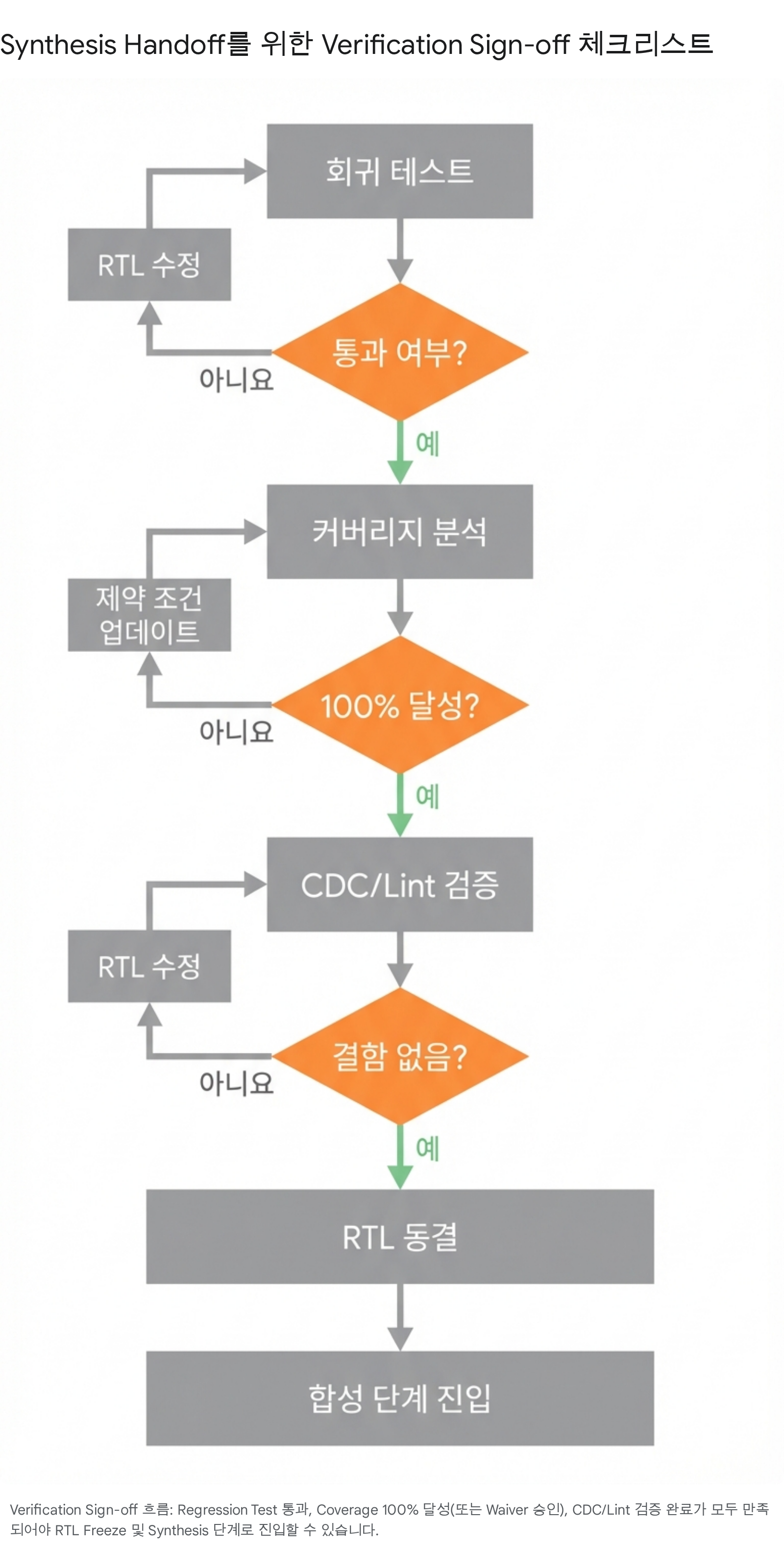
We have proven through a long journey that the RTL code operates as intended. For the Verification phase to be formally completed, the following three Sign-off Criteria must be satisfied.
- Regression Clean: All defined Testsuites passed without failure.
- Coverage Closure: Code Coverage and Functional Coverage have reached their target values (typically 100% or an agreed-upon figure), and reasonable Waiver approvals have been completed for any items not meeting the target.
- CDC/Lint Clean: All Clock Domain Crossing issues and RTL coding style violations have been resolved using static analysis tools.
Only when all these conditions are met is the RTL code declared Freeze.
This RTL code will no longer be modified and is now ready to proceed to the Logic Synthesis stage, covered in the next installment, where it will be converted into a gate-level netlist.
In reality, the first of the top three most critical stages in an ASIC project is determining when to perform the RTL Freeze. Completing this early allows subsequent design phases to finish sooner, enabling the semiconductor design to be taped out by the scheduled manufacturing process date. designs to the scheduled manufacturing process date.
Remember that Verification is not just simple testing; it is the final line of defense and the most critical engineering process that guarantees the chip's quality and reliability.