
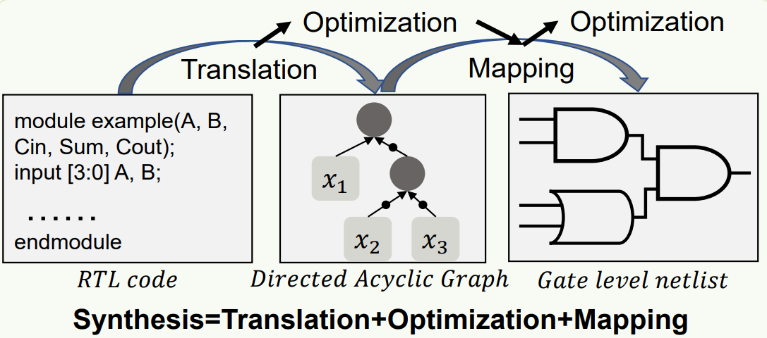
In modern semiconductor design, particularly in the ASIC (Application Specific Integrated Circuit) design flow, Logic Synthesis is the most critical transformation process that concretizes abstract human logic (RTL or HDL) into the physical reality of silicon (Gate-level Netlist).
In summary,
Logic Synthesis takes RTL as input and outputs a Gate-Level Netlist.
- RTL is a design specification that contains only the logical structure, without considering physical aspects.
- In subsequent stages like P&R and ECO, modifications are limited to placing and routing the circuit generated by logic synthesis by inputting coordinates, and slightly altering cell types.
- Regarding the PPA achieved in synthesis, even if higher PPA is desired, it is difficult to achieve significantly higher PPA in P&R or ECO.
- It is challenging to achieve significantly higher PPA in R&D.R is not easy to achieve a higher PPA than this.
- Translation (or Elaboration)
- Optimization
- Mapping
- Parsing & Inference:
- The tool checks for syntactic errors in the code and parses
alwaysblocks andassignstatements. The most critical aspect at this stage is Hardware Inference. - For example,
if-elsestatements are converted into multiplexers (MUX), andposedge clkstatements are converted into flip-flops.
- The tool checks for syntactic errors in the code and parses
- Architectural Selection:
- In RTL, arithmetic operators like
+and*are abstract concepts. During elaboration, the tool decides on an initial architecture to implement these operators.
- In RTL, arithmetic operators like
- For example, when implementing an adder, the tool must decide whether to use the Ripple Carry method, which is smaller in area but slower, method, which is area-efficient but slower, or the Carry Look-ahead method, which sacrifices area for high-speed operation.
- Structural Hashing: Prevents duplicate nodes with identical inputs and functions from being created during AIG generation, saving memory and encouraging natural logic sharing.
- AIG Rewriting: A technique that extracts subgraphs from the AIG and replaces them with functionally equivalent structures using fewer nodes. This is a powerful method that reduces the overall graph size through iterative local optimization.
- Setup Uncertainty: Set as the sum of clock jitter and expected clock skew. This reduces the number of valid clock cycles during timing analysis (Pessimistic), encouraging the tool to optimize more tightly.
- Hold Uncertainty: Since holds are typically 0-cycle checks, phase differences need not be considered. It primarily reflects only the expected clock skew. This acts as a margin to prevent violations caused by data arriving too early.
- Set Input Delay: The time it takes for data to travel from a Timing startpoint outside the current_design to reach the input pin of the current_design.
- Set Output Delay: The time required for data to leave the output pin of our current_design and arrive at the Timing endpoint of the current_design.
- Interpretation: The tool performs optimizations such as placing High Drive Strength Cells or reducing Logic Depth to ensure the time data reaches the output pin is less than
Clock Period - Output Delay.
- Interpretation: The tool performs optimizations such as placing High Drive Strength Cells or reducing Logic Depth to ensure the time data reaches the output pin is less than
- Increasing the frequency makes the chip operate faster. However, switching activity increases, leading to higher power consumption.
- Parallelizing logic increases the chip's bandwidth. However, the chip area increases.
- Design Rule Constraints (DRC): The library used for Logic Synthesis characterizes the library based on the following three criteria. Exceeding these values leads to inaccurate results because the foundry has not characterized those aspects.
- Min/Max Transition
- Min/Max Capacitance
- Timing Constraints (Setup Time): Core Performance Metric
- WNS (Worst Negative Slack): Represents the slack value of the path with the most severe violation (Critical Path).
- TNS (Total Negative Slack): The sum of all violation path slacks.
- Hold Time Constraints (Min Delay):
- During Logic Synthesis, the clock tree is ideal, making it impossible and inefficient to completely eliminate hold violations.
- Historically, the Wire Load Model was used, adding wire delay based on gate count. Today, 60% of the clock period is used as the setup margin, allocating 40% as setup margin, and focusing the P&R phase on hold time closure.
- Power & Area Optimization (Area Recovery):
- While satisfying the above conditions, reduce leakage power and area by downsizing gates on paths with positive slack or replacing them with low-power High-Vt cells (LVT → HVT). This is called Area Recovery.
- The Verilog input for Logic Synthesis will consist of various *.v files.
- By default, the synthesis tool iterates through each *.v file, performing optimizations on each one.
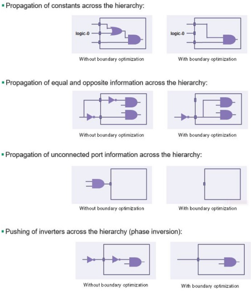
- Advanced Synthesis tools examine all *.v files at once from above and optimize the boundaries between *.v files. This is called Boundary Optimization.
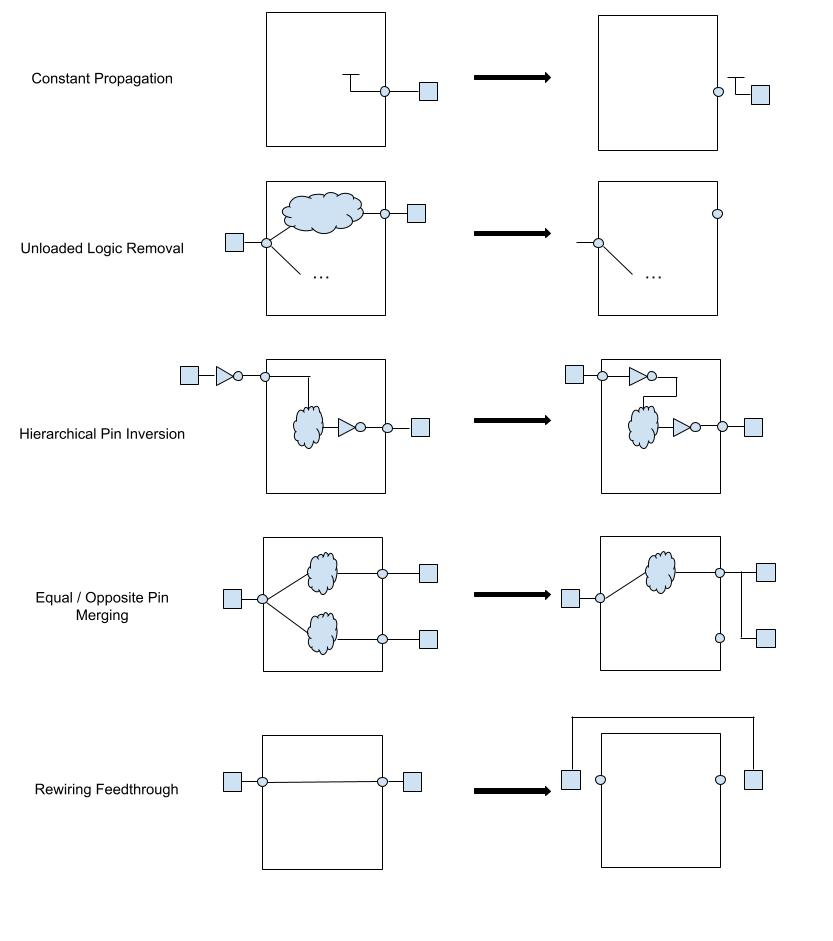
- Constant Propagation: If a specific input pin of a lower-level module is fixed to
0or1in an upper-level module, the tool enters the lower-level module and removes all logic related to that signal. This is a highly effective method for reducing unnecessary gates. - Hierarchical Pin Inversion: To improve timing, inverters are moved across module boundaries. In some cases, the phase of a module's input pin is inverted, and internal logic is modified according to De Morgan's laws to induce more efficient mapping.
- Feedthrough Optimization: If a signal merely passes through a module, detect it to create a bypass path or remove the port, reducing routing congestion.
- Constant Propagation: If a specific input pin of a lower-level module is fixed to
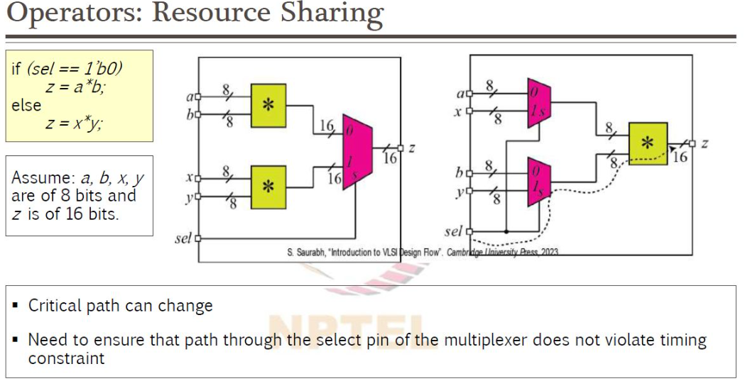
- Resource Sharing: If high-cost operators (e.g., Multiplier, Adder) operate at different times (e.g., selected by a MUX), instead of creating two, create only one and place the MUX upstream to share it. This drastically reduces area but adds logic upstream of the data path.(Multiplier, Adder) operating at different times (e.g., conditions selected by a MUX), create only one instance and place the MUX upstream to share it. This dramatically reduces area but introduces a trade-off: adding logic upstream in the data path can degrade timing.
- Retiming: A technique that balances delays between paths by moving the position of pipeline registers between combinational logic stages. For example, if a register follows long combinational logic and is followed by short combinational logic, moving the register forward allows increasing the clock frequency. It is enabled via the
optimize_registersorcompile_ultra -retimeoptions. - Cut Enumeration: Finds all subgraphs that can be created by cutting off (removing) inputs at specific nodes in the graph. For example, it explores whether a logic block with 4 inputs can be mapped to a single cell. This principle is similar to LUT mapping in FPGA synthesis.
- Cost-based Selection: There are countless ways to implement a single logic. To implement
(A+B), one could use a singleORgate, or a combination of aNORgate and anINVgate. The tool calculates the unique cost (PPA) for each pattern graph (Standard Cell) and uses Dynamic Programming to find the combination that minimizes the total cost required to cover the entire graph. - NLDM (Non-Linear Delay Model): Traditionally, delays are calculated using a two-dimensional look-up table (LUT) based on Input Transition Time and Output Load Capacitance. While sufficient for processes above 90nm, its accuracy diminishes below this threshold.
- CCS (Composite Current Source) / ECSM: In the latest fine processes, transistor operation is modeled as a Current Source to precisely reflect nonlinearity, the Miller Effect, and low-voltage behavior. Most synthesis for 28nm and below processes is currently performed based on CCS/ECSM models.
- Virtual Placement & Routing: Uses the same placement engine as actual P&R tools (IC Compiler2, FusionCompiler, Innovus) to determine the approximate positions of cells. This extracts RC parasitic components based on the actual distance (Manhattan Distance) between cells.
- Congestion Analysis and Mitigation: Detects congestion in advance during the synthesis stage, where excessive logic crowding in specific areas makes routing impossible. The tool prevents DRC violations by dispersing logic in congested areas (Spread) or modifying the structure.
- Reg2Reg: Paths between flip-flops. A core metric for chip performance. If there are significant violations in the Synthesis stage, it's hard to improve further after P&R phase, it's difficult to improve significantly afterward.
- In2Reg / Reg2Out: Paths to/from I/O interfaces. Affected by previously set
set_input_delay/output_delay. If other stages have margin, significant issues here may be avoided. - In2Out: Often, if constraints aren't applied here, entire cells might be deleted or massive buffers added, so be cautious.
- RTL Modification: The most powerful approach. Add pipeline registers or replace complex
if-elsechains with parallelcasestatements. - Utilize LVT Cells: Set the
compile_ultraoption to increase the usage of Low-Vt (LVT) cells, which have high leakage power but fast speed. Note this increases power consumption. - Path Group Weight: Use the
group_path -weightcommand to assign higher priority to specific path groups, forcing the tool to optimize those paths even at the expense of area. - Logic Cloning, Retiming, Boundary optimization can also be used to reduce it. These are things the P&R tool finds difficult to do on its own, and even if it does, it's very complex.
- It's best to view Synthesis as the final place to touch the Logic. If you try to fix these timing violations later in the ECO phase using things like ICG Cloning... tasks that take minutes in Synthesis can take hours in ECO.
- Hold Time Violation (Min Path) Resolution Strategy
- Principle: At the synthesis stage, the reliability of Hold timing is generally low. This is because buffers added without actual routing delays are likely to be removed again during the P&R stage or become inaccurate.
- Nevertheless, capturing significant Hold violation values (which vary by design) during synthesis helps reduce the burden on the P&R tool.
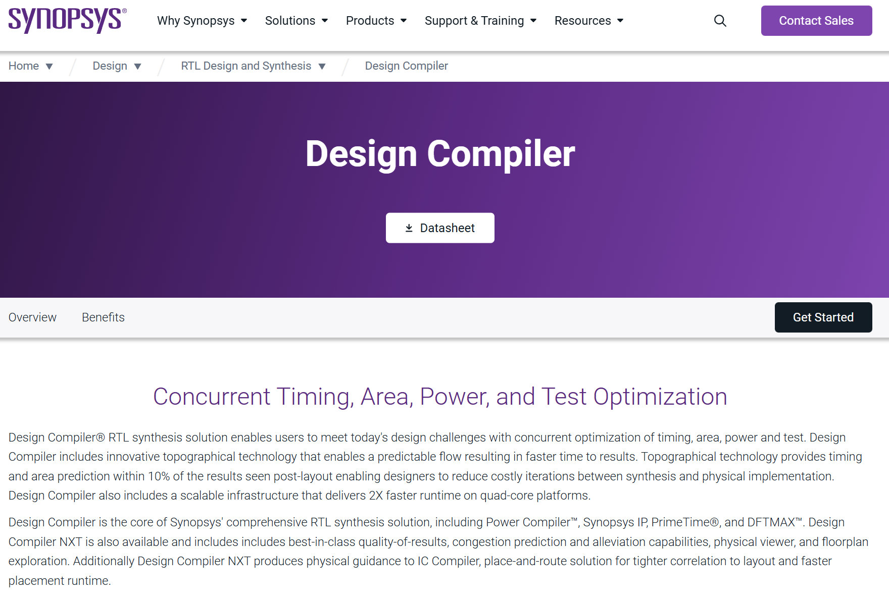
- Synopsys Design Compiler: Has long reigned as the de facto standard(de facto standard) for a long time. Its strengths are its robust ecosystem and stability, and it is enhancing integration with P&R through the Fusion Compiler platform.
- Cadence Genus: Although a latecomer to synthesis, it is gaining popularity because the P&R tool Innovus is highly favored by Physical Design engineers.
- Looking at the PD engineers around me, many prefer the combination of DesignCompiler and Innovus.
The netlist is a design diagram based on the cell library provided by the foundry, containing both physical and logical information. (It does not include coordinate values.)
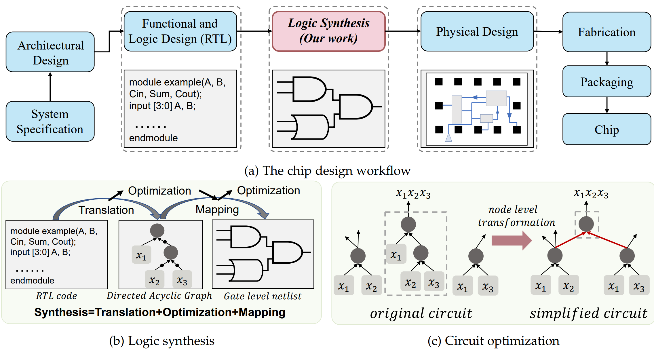
Synthesis occupies an absolute majority in the entire flow from RTL to GDSII.The initial PPA (Power, Performance, Area) metrics determined at this stage dictate the convergence of the subsequent Place and Route phase. If incorrect constraints are set during synthesis or structures that fail to reflect physical reality are generated, it will necessitate an enormous amount of overtime work during the back-end design process.
Synthesis-Process-Flow-and-Design-Convergence
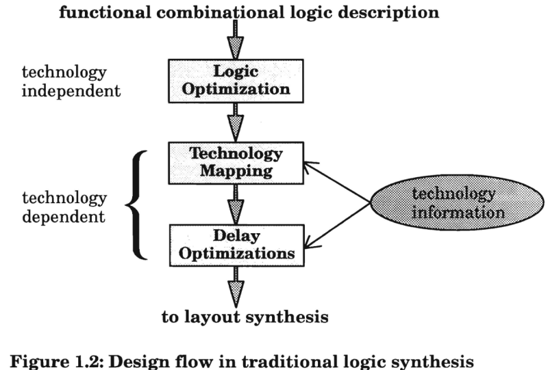
EC%83%81%ED%99%94-%EB%A0%88%EB%B2%A8%EC%9D%98-%ED%95%98%EA%B0%95%EA%B3%BC-%EC%B5%9C%EC%A0%81%ED%99%94%EC%9D%98-Conversion">1. Mathematics of Transformation: Descending Abstraction Levels and the Prelude to OptimizationLogic synthesis is fundamentally the process of solving a multidimensional optimization problem: minimizing Implementation Cost while maintaining Functional Equivalence. RTL code is a high-level abstraction easily understood by humans.Logic synthesis consists of three steps.
1.1 Parsing and Elaboration (Parsing & Elaboration): The World of GTECH
The first step in synthesis is converting HDL (Verilog/VHDL) text into an internal database structure that the tool can understand. This process is called elaboration. The initial netlist generated here uses the GTECH (Generic Technology) library, which is independent of specific process technologies.

1.2 Technology Independent Optimization
The netlist in GTECH state is logically simplified by applying the principles of Boolean Algebra. This step is performed independently of the Standard Cell, hence it is called 'Technology Independent'.
1.2.1 Boolean Optimization and Redundancy Removal
The most fundamental optimization is removing unnecessary logic. For example, A & 1 is reduced to A, and A | 0 is reduced to A. More complexly, it identifies and removes redundant connections within the circuit that do not affect the output, or replaces them with constants.This is an algorithmic extension of the K-Map principle. For large-scale circuits, heuristic methods like the Espresso Algorithm are used.
1.2.2 Common Subexpression Elimination
The tool analyzes the Data Flow Graph to find redundant operations.When F = (A * B) + C and G = (A * B) + D exist,the structure is modified so that the term (A * B) is calculated only once and its result is shared, rather than being computed separately. This reduces the number of gates and optimizes the area.
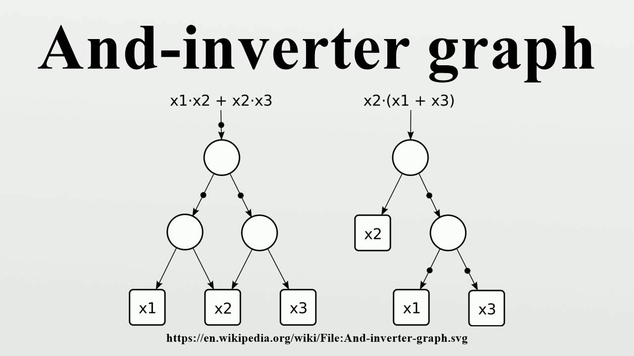
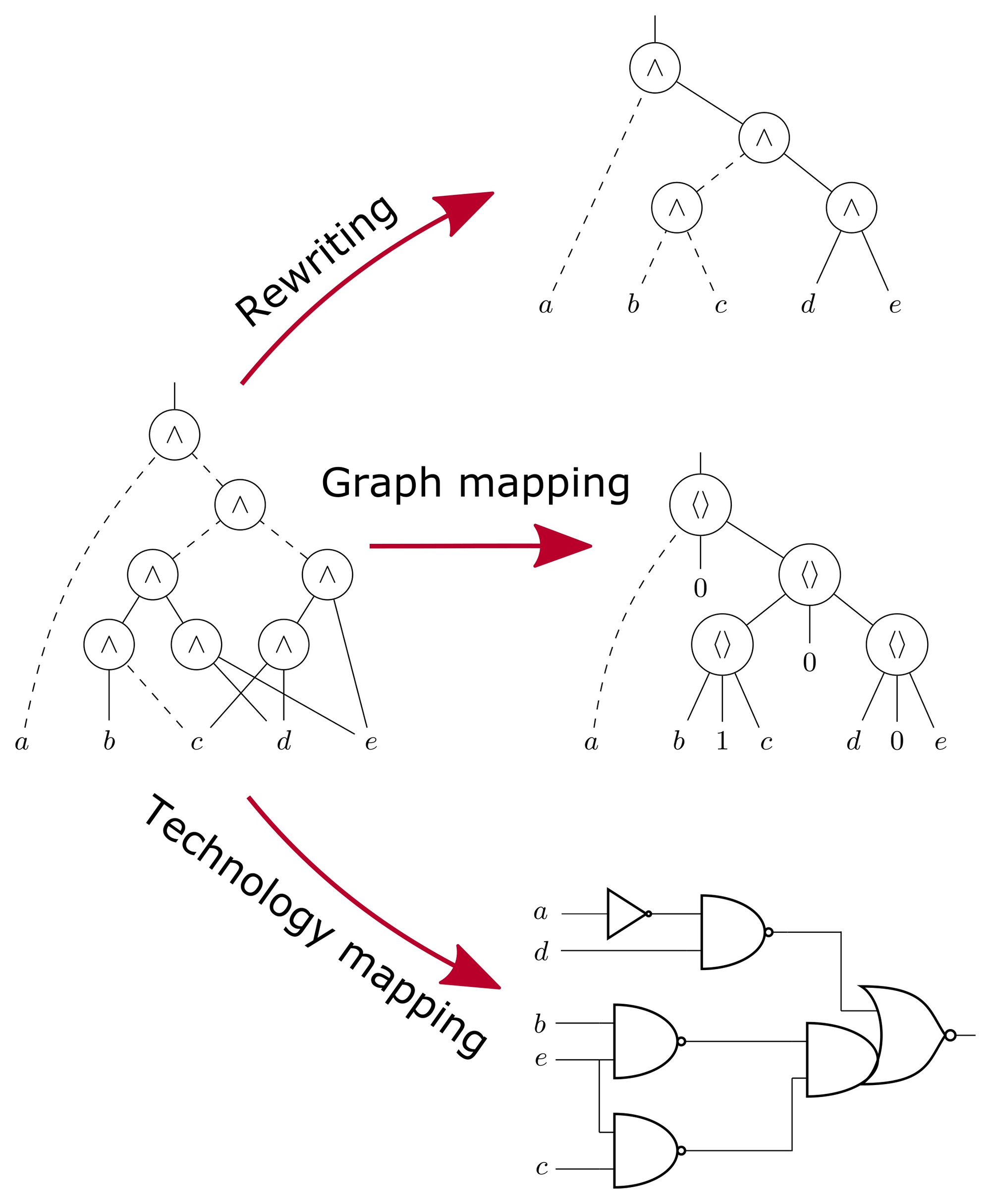
1.2.3 AIG (And-Inverter Graph) Based Optimization
Modern synthesis tools (especially ABC, Genus) represent logic using an And-Inverter Graph (AIG).ED%99%94">1.2.3 AIG (And-Inverter Graph) Based OptimizationModern synthesis tools (especially ABC and Genus) actively utilize the AIG (And-Inverter Graph) structure to represent logic.An AIG is a DAG (Directed Acyclic Graph) that represents all logic circuits using only 2-input AND gates and Inverters. While traditional BDDs (Binary Decision Diagrams) suffer from the drawback of memory usage increasing exponentially depending on variable order, AIGs are structurally resource-efficient.
2. Principles and Physical Interpretation of Design Constraints (Synopsys Design Constraints, SDC)
"Garbage In, Garbage Out." This is the most important adage in EDA. No matter how efficient a tool's optimization engine is, if the Constraints—the target values specified by the designer—are inaccurate, it will produce erroneous results.SDC (Synopsys Design Constraints) is not merely a configuration file; it is a standardized language that communicates Design Intent and Physical Environment to the tool.
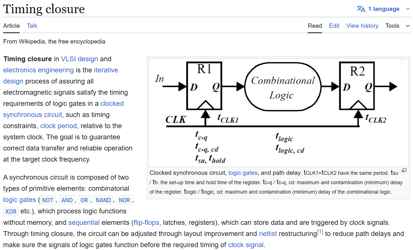
2.1 Clock Definition and Modeling: The Reference Point of Time
The clock is the reference for all synchronous digital circuits. The create_clock command defines the Clock Frequency, Duty Cycle, and Phase. However, the clock at the synthesis stage is assumed to be 'Ideal' since the actual physical Clock Tree has not yet been formed.
2.1.1 The Necessity of Clock Uncertainty
An Ideal Clock is a perfect square wave without Skew or Jitter, but the actual silicon environment is not like that. Therefore, the set_clock_uncertainty command must be used to preemptively secure a margin against potential variations that may occur after layout.
2.1.2 Virtual Clock and I/O Constraints
When constraining timing for a chip's primary ports, Virtual Clock is used to model the clock of an external device.strong> is used to model the clock of an external device. The virtual clock is not physically connected to any pin inside the chip, but it serves as a reference for functions like set_input_delay or set_output_delay.
2.2 I/O Time Budgeting
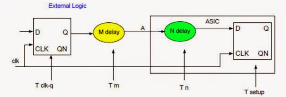
set_input_delay and set_output_delay are commands that inform the tool of the "time already used outside the chip(or will be used) outside the chip." The tool subtracts this value from the total clock cycle to calculate the Time Budget available for the chip's internal logic.p>
2.3 Timing Exceptions
Not all paths must operate within 1-cycle or 0-cycle. If you don't explicitly specify exception paths, the tool may waste area and power optimizing unnecessary paths or miss optimizing critical ones.Crucially, these methods should be used with extreme caution because they essentially say, "I'll give the timing check more leeway and see what happens." If you can achieve timing closure without them, it's safer not to use them.ED%8F%AC%EA%B8%B0-%EC%84%A0%EC%96%B8">2.3.1 False Path: Declaring Optimization Abandonmentset_false_path designates paths that are logically unreachable or where timing is unimportant.
2.3.2 Multicycle Path: Time Extension
set_multicycle_path is an instruction that allocates N cycles for paths difficult to complete within 1 cycle, such as multipliers or complex arithmetic operations.
3. Optimization: Cost Function and PPA Tradeoffs
Synthesis tools are not magic boxes. They are massive mathematical engines that find solutions minimizing the Cost Function amidst numerous constraints. This cost function is expressed as a weighted sum of conflicting factors: Performance, Area, and Power.
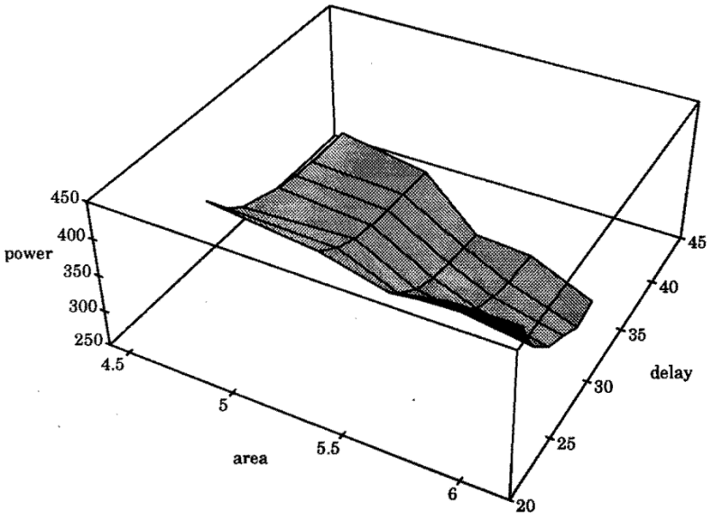
For example:In the past, a key metric was how many more chips could be placed on a wafer (enabling cheaper mass production?).Today, the core focus is on how much more bandwidth can be increased and how much yield can be improved.
3.1 Absolute Optimization Priority
When a tool cannot simultaneously satisfy all constraints, it operates according to the following strict priority order. Understanding this order is essential for analyzing synthesis results and tuning constraints.
3.2 Boundary Optimization and Hierarchy
Synthesis tools typically perform optimization at the module level. However, using advanced commands like compile_ultra enables optimization that crosses module boundaries.
3.3 Advanced Optimization Techniques: Retiming and Resource Sharing
4. Micro-level Principles of Technology Mapping
The process by which the assign y = a & b; code written by the RTL designer is transformed into a combination of NAND gates and INV gates on actual silicon is not a simple 1:1 substitution. It is a process that solves a highly complex algorithmic problem known as Graph Covering.
4.1 Boolean Matching
The tool converts the optimized Boolean Network into a graph form called the Subject Graph. Simultaneously, it converts the Standard Cells in the .lib file into a Pattern Graph representing each function. Technology mapping is the process of seamlessly covering the Subject Graph with Pattern Graphs.
4.2 Evolution of Delay Models
Accurate delay prediction is essential for precise cost calculation during the mapping stage.
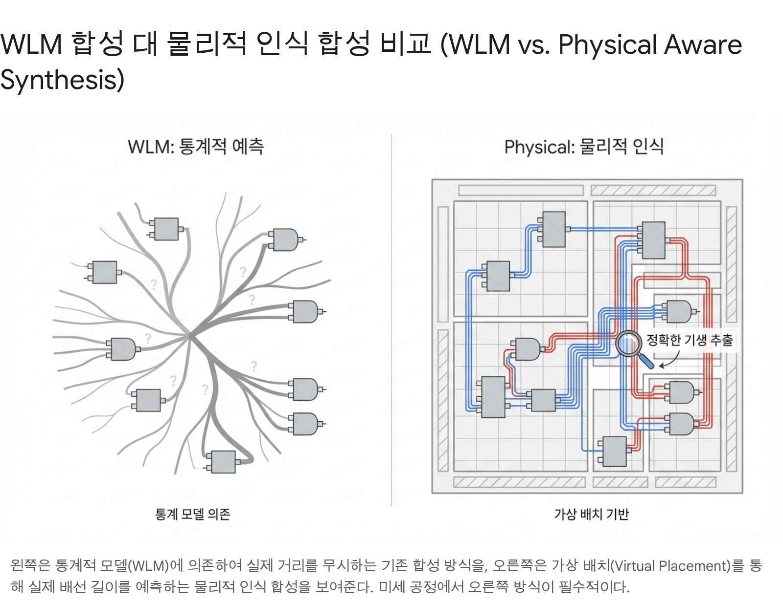
5.1 The Limits of WLM and the Emergence of Physical Synthesis
However, as we transitioned to 65nm, 28nm, and FinFET processes, the situation reversed. As line widths decreased, the Resistance ratio increased sharply, and Coupling Capacitance between lines came to account for nearly 50% of the total delay. WLM-based synthesis showed severe Correlation Issues with the actual post-P&R timing, leading to endless design iterations.As a solution, Physical Aware Synthesis emerged. Examples include Synopsys' Design Compiler Graphical/NXT (compile_ultra -spg) and Cadence's Genus iSpatial technology fall into this category. They call the Coarse Placement and Global Routing API of their own P&R engine within the synthesis engine to estimate how routing should be performed based on the current DEF, and then incorporate those values into the Logic Synthesis stage.
5.2 Core Functions of Physical Synthesis
6. Result Analysis and Timing Adjustment Strategy
Once synthesis is complete, engineers must analyze numerous reports and logs to verify the Quality of Results. This stage is the final quality gate before handing off data to the next process.
6.1 Timing Report Interpretation and Path Group
The timing report details the timing of all clock domains and clock paths.EC%84%9D%EA%B3%BC-path-group">6.1 Timing Report Interpretation and Path GroupThe timing report shows the journey from the Launch Flop to the Capture Flop. For analysis efficiency, the tool classifies paths into Path Groups based on their characteristics.
6.2 Setup/Hold Violation Fix Guide-%EC%88%98%EC%A0%95-%EA%B0%80%EC%9D%B4%EB%93%9C">6.2 Setup/Hold Violation Fix Guide
The timing correction strategy during the synthesis stage differs from that in the P&R stage because the routing has not yet been finalized.
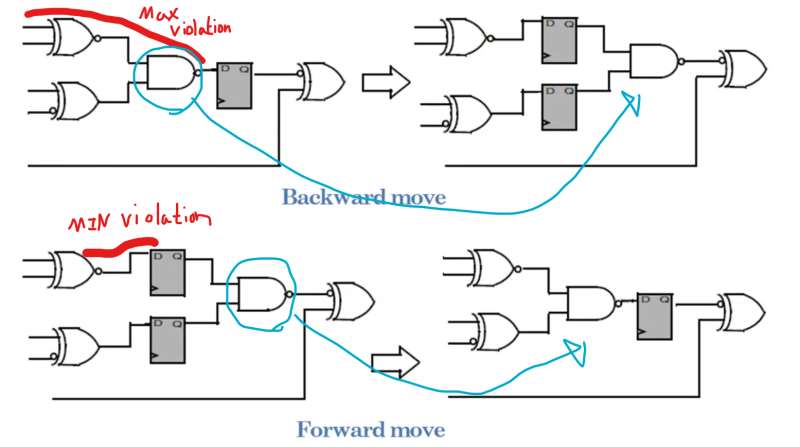
Setup Time Violation (Max Path) Resolution Strategy
Setup violations occur when data arrives too late.
Hold Time Violation (Min Path) Resolution Strategy
Hold violations occur when data arrives too quickly.-%EC%A0%84%EB%9E%B5">Hold Time Violation (Min Path) Resolution StrategyHold violations occur when data arrives too quickly.
7. Latest Tool Trends: Design Compiler vs Genus
Synopsys' Design Compiler (DC) and Cadence's Genus, which currently dominate the market, each possess distinct strengths.
R tool, Innovus, is highly popular among Physical Design engineers, its popularity is growing.
Looking at PD engineers around me, many prefer the combination of DesignCompiler and Innovus. The important thing is, if you only use one tool, you become dependent on it, making it difficult to switch to another tool. It's just a tool, after all.
Conclusion: You must become an engineer who masters the tools
Logic Synthesis is not a translator that converts RTL into gates.
- Operator: They try various approaches until link_design succeeds, compile when linked, and pass the generated netlist to P&R engineers.
- Expert: They interface with everything from RTL code reviews to meetings with P&R engineers to requesting new feature development from EDA, researching how to achieve the best PPA.
Logic Synthesis is a highly engineered process that solves equations with tens of millions of variables under physical and logical constraints.
Tools are not perfect. Only engineers who can communicate precise 'intent' to the tool via SDC, interpret the tool's 'thoughts' through logs and reports, understand physical phenomena, and know how to 'improve' the RTL structure can achieve the best PPA results.
Junior engineers should not remain mere operators pressing tool buttons. Instead, they must ask:
"How do these constraints affect the tool's cost function?"
"How does this RTL structure appear as a pattern to the mapping algorithm?"
How does this constraint affect the tool's cost function?"
"What pattern does this RTL structure represent to the mapping algorithm?"
"What synthesis-related papers are in this SNUG conference?? What are other companies doing??"
They must constantly ask these questions. Only when the answers to these questions accumulate will you truly become an 'Architect' in the fullest sense.