
RTL goes through a significant number of EDA tools before tape-out. Could this process ever be completely bug-free? What if a tool bug caused an extra inverter to be added?
Formal Verification, specifically Logic Equivalence Checking, LEC is an essential methodology in modern ASIC design flows.
Unlike simulation, LEC does not use test vectors. Instead, it is a methodology that performs static analysis to ensure two design representations exhibit identical behavior mathematically and logically across all possible cases.
The primary purpose of LEC is to verify integrity during design transformation processes. When RTL (Register Transfer Level) code is converted to a Gate-level Netlist through Logic Synthesis, or when P&R tools modify logic for timing optimization, or when scan chains are inserted during the DFT (Design for Testability) process, it verifies that the original designer's intent (Golden Design) is perfectly preserved in the transformed design(Revised Design).
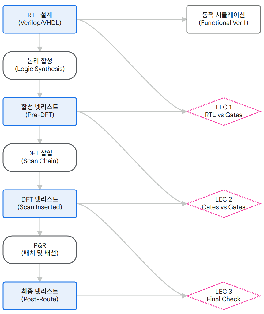
As shown in the diagram above, LEC is performed iteratively at various stages: RTL vs. synthesis netlist, synthesis netlist vs. DFT netlist, and final layout netlist verification.
This acts as a safeguard, immediately capturing logical defects caused by potential tool bugs or user errors at each stage, thereby preventing costly re-spin costs.
Binary Decision Diagrams, (BDD) and Boolean Satisfiability, (SAT).
2.1 Miter Circuit Construction and Refutation-Based Verification
The fundamental principle of LEC is to compare two circuits (Reference and Test) to find whether 'even a single instance' exists where the outputs differ. To achieve this, the tool constructs a virtual Miter circuit. The Miter circuit structure connects the identical input ports of the two circuits together and links the corresponding output ports via XOR gates.
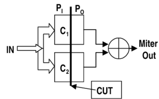
Logically, an XOR gate outputs '1' only when its two inputs are different. Therefore, the goal of LEC tools boils down to answering the question: "Does an input combination exist where the XOR gate outputs '1'?"
- If such an input combination (counterexample) exists, the two circuits are non-equivalent.
- If the XOR output is always '0' for all possible inputs, the two circuits are Equivalent.
This approach is based on counterfactual thinking, which suggests that "finding differences" can be algorithmically more efficient than "proving equivalence".
2.2 Binary Decision Diagrams, BDD
BDD, which formed the foundation of early LEC tools, is a data structure that represents Boolean expressions as a directed acyclic graph (DAG). The most powerful feature of BDD is its Canonical Form.
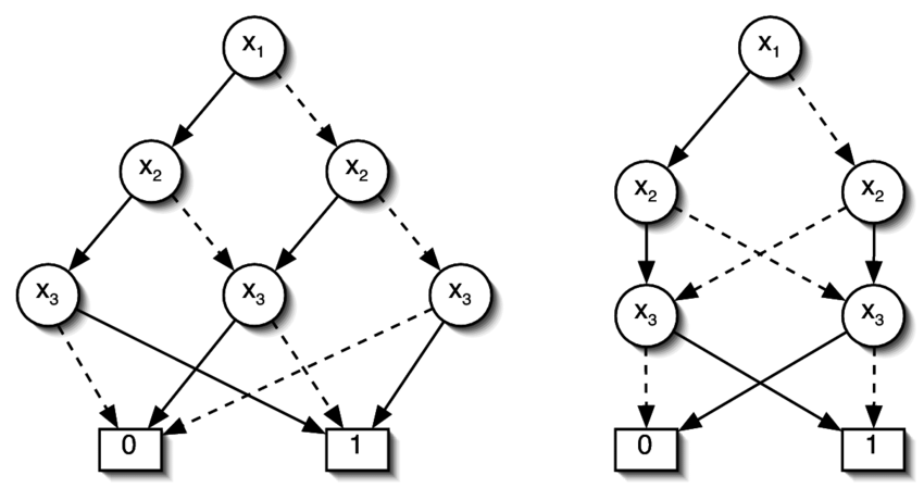
Canonical Form is a standard representation that fully expands a Boolean function based on input combinations. This means that for a given Boolean function, if the Variable Ordering is fixed, the shape of the BDD graph representing that function is unique. This dramatically simplifies the verification process.
After generating the BDDs for the Golden Circuit and the Revised Circuit, we can verify whether the two graphs have identical structures in memory (i.e., whether the paths from the Root Node to the Terminal Node match) simply by comparing pointers.
However, BDDs have a critical weakness. Specifically, the Memory Explosion problem. For complex logic with many Input Variables or specific arithmetic circuits like Multipliers, the number of BDD Nodes increases exponentially, exceeding physical memory limits. This limitation prevented BDD-based verification from handling entire large-scale SoC designs. SAT is an algorithm that searches for a Variable Assignment that makes a given Boolean expression (primarily CNF, Conjunctive Normal Form) True.
From the LEC perspective, the SAT Solver finds an Input Condition that makes the output (XOR) of the Miter circuit '1'. Unlike BDDs, SAT does not attempt to store the entire Truth Table compressed. Instead, it finds the Solution using Depth First Search (DFS), Backtracking, and Learning techniques.
- Advantages: Significantly lower memory usage compared to BDDs and operates efficiently even on large circuits. Particularly fast at finding Counter-examples.
- Disadvantages: For certain problems, the search space can be too large, making finding a solution very time-consuming (NP-Complete problems). Therefore, modern LEC tools adopt a Hybrid approach, either combining BDD and SAT, or automatically selecting the appropriate engine based on the circuit structure.
2.4 Logic Cone Partitioning
Solving the entire chip as a single massive Boolean equation is impossible. Therefore, LEC tools verify the design by breaking it down into small units called Logic Cones.
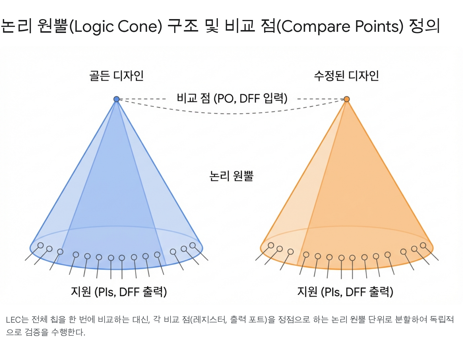
- Compare Points (Key Points): These are the elements that serve as reference points for verification. They primarily include the Primary Output, the input (D-pin) of the Flip-Flop, and the input pins of the Black Box.
- Formation of the Logic Cone: Each Compare Point is designated as an Apex. All Primary Inputs, Flip-Flop outputs (Q-pin), Black Box output pins, etc., as the Base to define the Combinational Logic area.
LEC maps the Golden and Revised designs 1:1 using these Logic Cone units, then independently verifies that each pair is equivalent. This solves the overall problem complexity using a 'Divide and Conquer' approach.
3. Detailed Steps of the LEC Verification Process
When operating tools like Synopsys Formality or Cadence Conformal LEC in actual industrial settings, the verification process generally follows a four-step cyclical structure: Setup, Mapping, Compare, and Debug. Each step includes essential detailed tasks to ensure verification reliability.
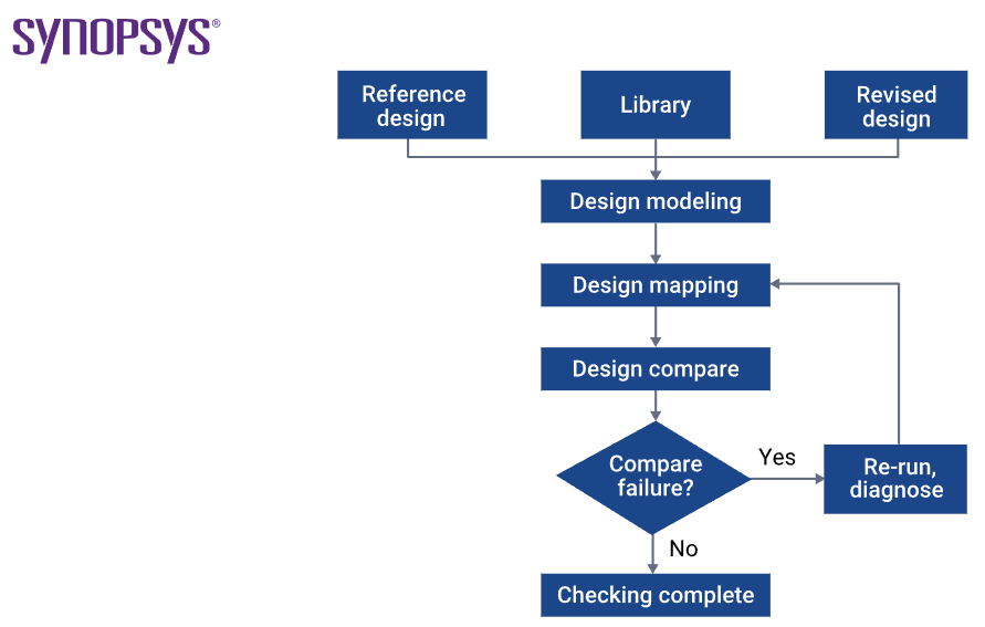
3.1 Step 1: Design Modeling, Setup - Building the Verification Environment
The setup phase involves loading the two designs to be compared (Reference/Golden and Implementation/Revised) into the tool and configuring the correct verification environment. Minor errors in this step can lead to significant debugging costs later, so utmost care is required.
- Library Loading: Load the Standard Cell library, I/O pad library, and black-box models such as memory or Analog IP.
- Cadence Conformal supports both
.lib(Liberty) and Verilog models for simulation (.v). The important point is that both designs must reference libraries with identical functional definitions. - Read Design:
- Golden Design: This is the design used as the verification standard. It is primarily RTL (Verilog, VHDL, SystemVerilog) code. When reading RTL, parameters are finalized and the hierarchy is generated through the
elaborateprocess. - Revised Design: This is the design used for comparison. It is the Netlist generated after Synthesis or the Netlist after P&R.
- Golden Design: This is the design used as the verification standard. It is primarily RTL (Verilog, VHDL, SystemVerilog) code. When reading RTL, parameters are finalized and the hierarchy is generated through the
- Constraints Setup: These are guidelines that help the LEC tool correctly interpret the design.
- Set Constant: The netlist contains scan chain logic for testing, making it structurally different from the RTL. Therefore, the
Scan Enablesignal must be fixed to 0 (or its inactive value) to force the tool to verify only the functional path, not the scan path. - Undriven Signals Handling: Define how floating inputs (ports with no connected inputs) should be interpreted: '0', '1', 'Z' (High-Z), or 'X' (Don't Care). Incorrect settings can cause unnecessary discrepancies.
- Set Constant: The netlist contains scan chain logic for testing, making it structurally different from the RTL. Therefore, the
3.2 Step 2: Design Mapping - Linking Comparison Targets
Mapping is the process of establishing a 1:1 correspondence between the comparison Key Points of the Golden design and the comparison points of the Revised design. For the Synopsys Tool chain, a file called SVF assists with this.
- Name-based Mapping: Used when Register or Port names are identical or follow a regular pattern. The tool primarily attempts name matching first.
- Function-based Mapping: Even if names have changed (e.g., when synthesis tools arbitrarily rename during optimization, or when a Data bus Flip Flop undergoes Banking or De-banking to become a Multibit flopflop),, it attempts mapping by analyzing the similarity of the logical function (Logic Cone) driving the port. This is computationally expensive but essential for verifying netlists where naming rules are broken.
- Renaming Rules: Users can define mapping rules directly. For example, if an RTL `reg` is renamed to `reg_0_` in the netlist, the tool can be instructed to map it by replacing `_` with ``.
- Unmapped Points Analysis: Unmapped points are excluded from comparison. It is crucial to verify whether this is intentional (e.g., removal of unused logic) or an error (e.g., missing renaming rules).
This is where Unmatch lists occur. Not only LEC Fail, but Unmatch lists also require the verifier's analysis.
3.3 Step 3: Design Compare
Mapped Point pairs undergo LEC verification. The tool employs a multi-stage strategy to maximize efficiency.
- Random Pattern Simulation: First, inject thousands of Random Input Patterns to quickly compare output values. If a Mismatch occurs at this stage, it is immediately judged as Non-Equivalent, saving costly Solver Resources.
- Structural Analysis and Formal Verification: For points passing the Random Pattern test, we attempt Formal Proof using an SAT or BDD Solver.
Results are classified into the following four categories:
- Equivalent: The output is identical for all input combinations (verification successful).
- Non-Equivalent: Outputs differ for specific inputs (Setup Issue or Functional Bug).
- Inverted-Equivalent: Outputs are exactly opposite (e.g., mapping of Q and Qbar). This may be functionally equivalent (if Phase Inversion is allowed), but requires careful verification. This primarily occurs in circuits with massive Multipliers or other Arithmetic Logic, or those with extremely deep Logic Depth.
3.4 Step 4: Debug - Root Cause Analysis and Fix
Compare Result is 3.4 Step 4: Debug - Root Cause Analysis and Fix.
3.4 Step 4: Debug - Root Cause Analysis and Fix
Compare Result is 3.4 Step 4: Debug - Root Cause Analysis and Fix.
3.4 Step 4: Debug - Root Cause Analysis and Fix
Compare Result is 3.4 Step 4: Debug - Root Cause Analysis and Fix.
4. Handling Synthesis Optimization and Structural Transformations
The greatest challenge in LEC verification is that RTL and netlists are structurally very different. Logic synthesis tools (Design Compiler, Genus, etc.) drastically transform the logical structure of RTL to optimize Area, Power, and Timing. If the LEC tool fails to understand these structural transformations, it will incorrectly determine a false negative(False Negative).
4.1 Combinational Logic Optimization
The most fundamental optimization is logic simplification using Boolean Algebra laws.
- Constant Propagation: When specific inputs are fixed as constants, the related logic is removed or simplified. LEC tools may also recognize this as an error if they are unaware of the same constant constraints.
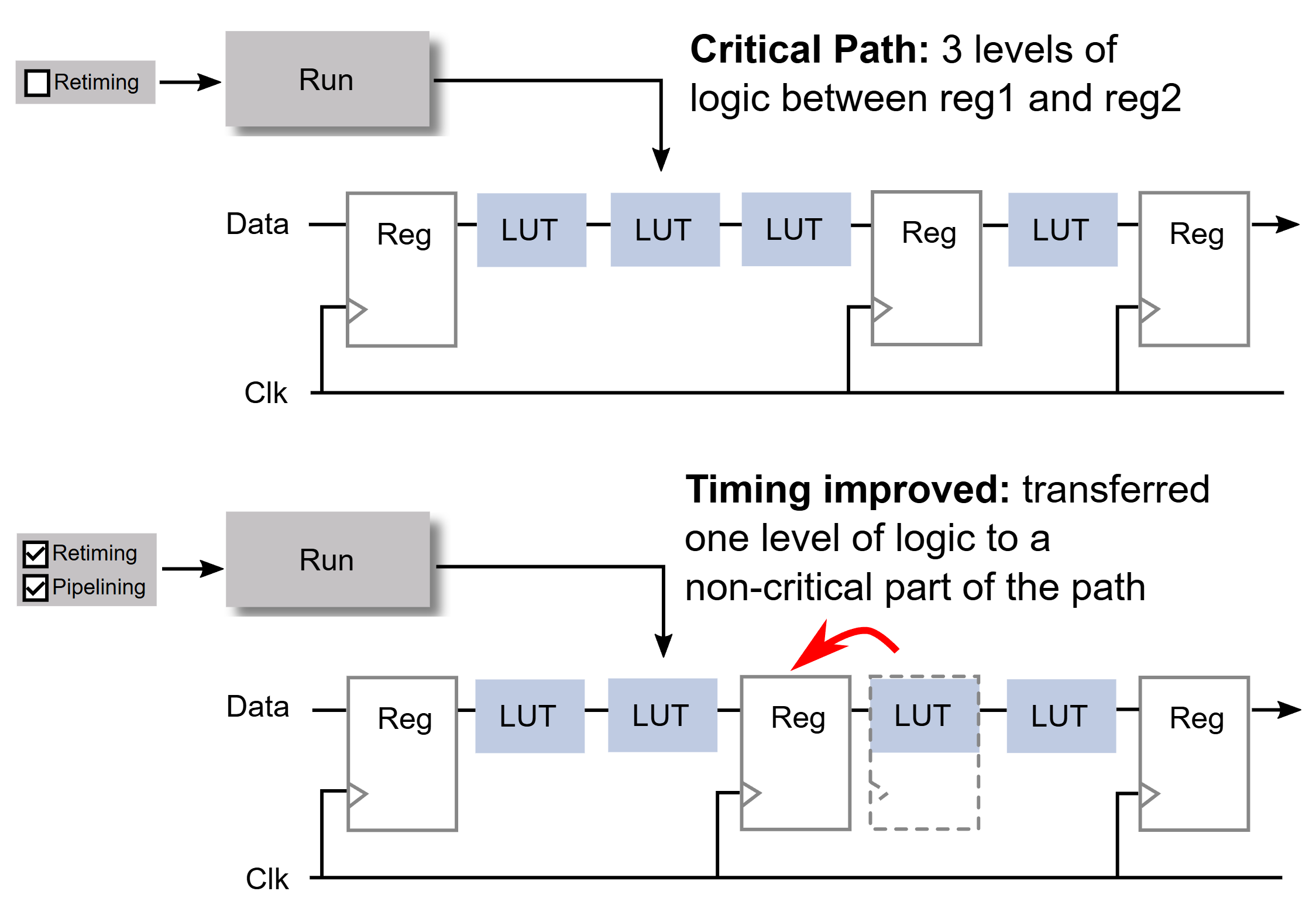
- Retiming: Retiming is a technique that physically moves registers to the opposite side of combinational logic to reduce the delay time of the critical path. In this case, the register locations in the RTL and netlist differ, making a 1:1 mapping impossible.
- Solution: The Setup Verification File (SVF) or guide file generated by the synthesis tool is essential. This file contains information stating "RTL register A has moved to netlist register B," allowing the LEC tool to reference it and reset comparison points.
- For details, refer to the Formality® Automated Setup File (SVF) Manual.
- However, SVFs often contain bugs. Using an SVF can cause failures, while omitting it may result in a pass.
- Pipeline Register Optimization
- FSM Re-encoding
- Retiming: Retiming is a technique that physically moves registers to the opposite side of combinational logic to reduce the delay time of the critical path. In this case, the register locations in the RTL and netlist differ, making a 1:1 mapping impossible.
- Ungrouping: Synthesis tools often break down the boundaries of submodules (Ungroup) and merge them with parent modules to flatten the hierarchy, improving optimization efficiency.
- Issue: When module boundaries disappear, hierarchical comparisons become impossible. The entire design must be flattened for comparison, drastically increasing verification time. Additionally, name changes like
submodule/regbecomingsubmodule_regcause mapping failures. - Solution: Utilize automatic name mapping features, or for critical modules, apply the `set_ungroup false` attribute during synthesis to preserve the hierarchical structure.
- Issue: When module boundaries disappear, hierarchical comparisons become impossible. The entire design must be flattened for comparison, drastically increasing verification time. Additionally, name changes like
- Boundary Optimization: This technique involves moving logic across module boundaries(e.g., pushing inverters outside the module), or propagating constants from input ports internally. This also causes mismatches at boundary pins during hierarchical comparison, so options like
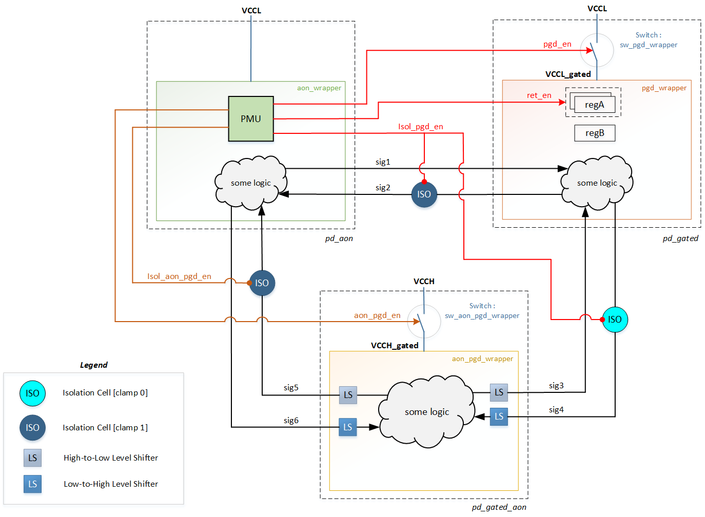
set flatten model -boundary_optimizationmust be enabled in LEC settings. - Isolation Cell: This cell clamps a signal to a specific value (0 or 1) when it transitions from a power-off domain to a power-on domain. The LEC tool verifies that the isolation rules defined in the UPF(Isolation Strategy) defined in the UPF. If isolation cells are missing or control signal connections are incorrect, inconsistencies occur.
- Level Shifter: Responsible for signal transfer between domains with different voltage levels. Functionally similar to a buffer, but LEC must verify compliance with voltage level rules.
- State Retention Cell: A special register that retains data even when power is off. LEC must handle the mapping between regular registers and Retention registers, requiring the library model to be loaded accurately.
- Functional ECO: This process involves modifying the RTL and then applying the minimum necessary patches to the existing netlist to make it identical to the RTL. Tools like Conformal ECO compare the modified RTL with the existing netlist and automatically generate the patch logic needed to resolve the differences.
- Utilizing Spare ECO Cells: If tape-out is complete and the FEOL process has already been finished, bugs must be fixed by using spare gates (Spare Cells) pre-distributed within the chip and modifying the BEOL Metal layer. LEC tools can generate an optimal patch netlist by inputting a list of available Spare Cells.
Logic Replication & Merging: Gates with large fan-out are replicated to resolve timing issues, or conversely, identical logic is merged to reduce area. The LEC tool must be able to handle these many-to-one (N:1) or one-to-many (1:N) mappings.ED%99%94-sequential-logic-optimization">4.2 Sequential Logic OptimizationOptimization that modifies not only combinational logic but also registers (flip-flops) themselves makes verification more difficult.
4.3 Hierarchy Modifications
The design hierarchy is also subject to optimization.
5.LEC with UPF for Low-Power Design
The application of low-power techniques is essential in modern mobile and IoT chip design. The introduction of Multi-Voltage Domain and Power Gating technologies adds new complexity to LEC verification.
5.1 UPF/CPF and Power Intent
The RTL code itself contains no information about the Power Network. Information such as Power domains, Isolation, and Level Shifters is defined in separate files: UPF (Unified Power Format) or CPF (Common Power Format).During LEC verification, these UPF/CPF files must be loaded together. The tool uses this information to insert virtual Power Logic into the RTL model, making it comparable to a netlist containing actual power devices.
5.2 Low-Power Cell Verification Issues
6. ECO (Engineering Change Order) and LEC

In the later stages of chip design, especially when bugs are discovered just before P&R or mask fabrication, instead of re-synthesizing the entire design, a FECO (Functional Engineering Change Order) is performed to modify only the minimum number of gates. The LEC tool also plays a key role in the ECO process.strong> is performed, modifying only the minimum number of gates instead of redoing the entire synthesis. LEC tools also play a crucial role in the ECO process.